Download
1 / 54

E N D
BMS 524 - “Introduction to Confocal Microscopy and Image Analysis”2 Credit course offered by Purdue University Department of Basic Medical Sciences, School of Veterinary MedicineMay, 1996J.Paul Robinson, Ph.D.These slides are intended for use in a lecture series. Copies of the graphics are distributed and students encouraged to take their notes on these graphics. The intent is to have the student NOT try to reproduce the figures, but to LISTEN and UNDERSTAND the material.Lecture 2The Principles ofConfocal Microscopy
Confocal Microscopy The term “confocal” means “having the same focus” This is accomplished by focusing the condensor lens to the same focal plane as the objective lens.
Confocal Microscopy Reduced blurring of the image from light scattering Increased effective resolution Improved signal to noise ratio Clear examination of thick specimens Z-axis scanning Depth perception in Z-sectioned images Magnification can be adjusted electronically
Conventional Fluorescence Confocal The difference in resolution can be significant in those specimens which are too thick to fit entirely within the focal plane of the lens.
Optical section of an aphid showing internal structure of an intact animal
If this is coupled with a point source of illumination and a matching point source of detection Pinhole 1 Pinhole 2 Specimen Detector Objective Lens Condenser Lens Modified from: Handbook of Biological Confocal Microscopy. J.B.Pawley, Plennum Press, 1989
Modern confocals use the objective lens for both focusing the illumination and focusing the image. Because this is necessarily the same focal plane they are “confocal” by default.
Arc Lamp Fluorescent Microscope Excitation Diaphragm Excitation Filter Ocular Objective Emission Filter
Laser Confocal Principle Excitation Pinhole Excitation Filter PMT Objective Emission Filter Emission Pinhole
In a confocal microscope only a relatively small portion of the specimen is illuminated at a time whereas in a conventional fluorescence microscope a much broader area is illuminated.
If the source of illumination is truly a point and it is focused to a point then only a single point in the specimen will imaged at any one time. Either the specimen must be moved to create a complete view or the beam must be scanned in a raster pattern.
One way to accomplish this is to pass the illumination through a series of pinholes that have been arranged in a pattern. As this disk is spun it will create a raster pattern and the light coming back through the pinholes will be confocal. The pinholes in a spinning disk system act as both the point sources and confocal apertures.
Spinning disk confocals: • Can image in “real” time provided that the disk is spun quickly enough • Can use a variety of light sources • Can be retrofitted to many existing fluorescence microscopes
Spinning disk confocals: • Are inefficient and require a very bright illumination and fluorescence • Cannot use sensitive light detectors such as photomultiplier tubes
Scanning Galvanometers Point Scanning Mirrors control beam movement in X/Y raster pattern x y Laser out To Microscope Laser in
Some scan mirror systems are able to be rotated which can result in a rotation of the raster pattern
By creating an image in a point by point manner the confocal microscope functions as a point scanning/signal detecting device and like an SEM magnification can be increased by scanning a smaller portion of the specimen
Imperfections in conventional light optics usually restrict useful zoom to 6X or less.
A modern confocal system consists of the microscope, associated lasers, the scan head with detectors and confocal apertures and a computer system that controls the scanning, adjusts the illumination, collects the signal, displays the images and stores the data for later image processing and analysis.
A laser scanning confocal microscope has many components including a way for several different lasers to provide excitation wavelengths and several separate detectors for various emission wavelengths
Although confocal microscopy can be done in the reflected (light backscattered) or even transmitted mode most systems are optimized for fluorescence. When excited to a higher energy state through the absorbance of a high energy photon a fluorochrome can dissipate the excess energy through the emission of a lower energy electron.
Arc Lamp Fluorescent Microscope Excitation Diaphragm Excitation Filter Ocular Objective Emission Filter
Light Sources - Lasers • Argon UV ArUV 351-364 nm • Solid State Violet 405 nm • Argon Ar 488-514 nm • Krypton-Ar ArKr 488-568-648 nm • Helium-Cad HeCd 442 nm • Helium-Neon GreNe 543 nm • Helium-Neon HeNe 633 nm
Excitation - Emission Peaks % Max Excitation at 488 568 647 nm Fluorophore EXPeak EM peak DAPI 358 461 0 0 0 FITC 496 518 87 0 0 Bodipy 503 511 58 1 1 Tetra-M-Rho 554 576 10 61 0 L-Rhodamine 572 590 5 92 0 Texas Red 592 610 3 45 1 CY5 649 666 1 11 98
Since the illumination wavelengths available are often limited the selection of matching fluorochromes is very important.
In a conventional confocal scan head the photons returning from the specimen are separated based on their energies (color) by passing them through a series of filters and collecting each on separate PMTs
Since they first became available in the late 1980’s laser scanning confocals have undergone many changes and advances.
One significant advance is how some systems separate the emission spectrum (signal) by wavelength and using slits sample those specific wavelengths using separate PMTs.
One of the advantages of having separate control over the collection of different emission spectra is the ability to create evenly balanced double, triple, and even quadruple labeled images. Each of the signals can be collected simultaneously and merged afterwards.
Spectral properties of the available dyes limit the experimental freedom. • Often it is even difficult to clearly separate two fluorescence markers. • With more markers, the problem grows increasingly complex. Cross-talk between the FP variants at the excitation and emisson level
Fluorescent Proteins are essential for life science studies. However, overlapping emission AND excitation spectra and corresponding crosstalk makes combinations difficult for imaging! (especially true for multiphoton imaging) Heavy overlap!
GFP and YFP (Distance of emission peaks ca. 12nm) A431 cells expressing GFP, Rab11-YFP GFP YFP overlay This type of separation is nearly impossible to accomplish with conventional filters, especially for weakly fluorescent samples
A focus motor can move the stage in precise increments so that multiple images from consecutive planes can be individually scanned and saved.
By collecting a series of images of the specimen at different distances from the lens (focal planes) a through-focus series or “Z-series” can be created.
The ability to collect data in the X,Y, and Z dimensions enables one to create an image of the specimen as if it were be observed from an orthogonal plane.
Stereo pair images can be created from a stack of confocal images by a technique known as “pixel shifting” In pixel shifting two separate 2-D projections of the data set are created by shifting adjacent image planes slightly out of registry creating a pseudo-left and pseudo-right projection.
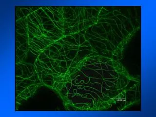
The two images can be colorize to produce an anaglyph stereo pair. (PC12 cell stained for microtubules)
Stereo Anaglyph Two dimensional projection of focus series
3D Image Reconstruction y z x By accessing information in all three dimensions a 3-D reconstruction of the data is possible
3D Image Reconstruction y y y z z x
3D Image Reconstruction y y z z x y
Conventional Volume Rendering Confocal
Fly Brain Optical sections of cornea
Volume renderings can be manipulated as if they were actual 3-D specimens
Applications • Probe Ratioing • Calcium Flux (Indo-1, Fluo-3) • pH indicators (BCECF, SNARF) Molecule-probe Excitation Emission Calcium - Indo-1 351 nm 405, >460 nm Magnesium - Mag-Indo-1 351 nm 405, >460 nm Calcium-Fluo-3 488 nm 525 nm Calcium - Fura-2 363 nm >500 nm Calcium - Calcium Green 488 nm 515 nm Phospholipase A - Acyl Pyrene 351 nm 405, >460 nm