Download
1 / 41
410 likes | 422 Views
Explore the benefits of layered architectures in networks, understand the importance of protocols and services, and delve into detailed examples such as web browsing, email communications, and more. Gain insights into the TCP/IP model, OSI reference model, and socket API utilities.

E N D
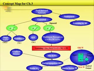
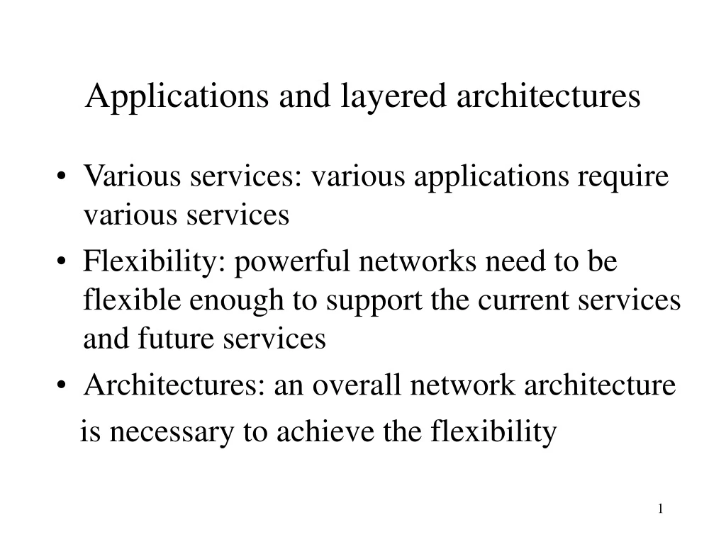
Applications and layered architectures • Various services: various applications require various services • Flexibility: powerful networks need to be flexible enough to support the current services and future services • Architectures: an overall network architecture is necessary to achieve the flexibility
Layered architectures • Layers: grouping the common functions • Benefits of layers: • Simplicity: easy to design once layers and their interaction are defined clearly • Flexibility: easy to modify and develop networks by separate layers modifications • Incremental changes: add new layers, add new functions to a layer
Three obvious tasks (layers) • Transport of data across the network from one end to the other • Routing/forwarding of packets across multiple hops • Transfer of a frame from one interface to another (i.e., one hop).
Big picture of layered architectures • Web browsing and e-mail examples • OSI reference model (Seven layers) • TCP/IP architecture • Detailed end-to-end examples to complete big picture of layered architectures • Socket API and other utilities
Terminology • Client/Server model: the most typical interaction between two parties within networks • Client: the process making requests • Server (Daemon): the process waiting and receiving requests, processing the requests and returning results • Protocols: a set of rules governing how two communicating parties are to interact. • Service: a protocol will provide a service • Layers’ protocols: each layer carries out a specific set of functions using its own protocol, and builds on the services of the layer below it (provides a service to its upper layer).
Example—HTTP and Web Browsing • HTTP: HyperText Transfer Protocol • Rules by which the (HTTP) client and server interact so as to retrieve a document and how the request and response are phased • Client sets up a two-way connection before request • Client generally carries out DNS (Domain Name Service) to find IP address of server
Event User selects a document HTTP Client locates the server host and sets up a two way connection HTTP client sends message requesting document HTTP server listing on TCP port 80 interprets message Message content Get /infocom/index.htm HTTP/1.0 Retrieve a document from the Web
Event HTTP server sends a result code and a description of information that the client will receive HTTP server reads the requested file and sends the file through TCP port HTTP server disconnects the connection Text is displayed by the client browser, which interprets HTML Message content HTTP/1.1 200 OK Server: Apache/1.2/5 FrontPage 3.0.4 Content-Length: 414 Content-Type: text/html <html> <head> <title>IEEE Infocom’99—The future is Now … Retrieve a document from the Web (cont.)
HTTP client/server interaction Request HTTP server HTTP client Response Figure 2.1
HTTP client HTTP server Ephemeral Port 80 Port # GET 80, # TCP TCP #, 80 STATUS • TCP provides a pipe between HTTP client and HTTP server • Transfer of message between HTTP client/server is virtual, indirect • HTTP is said to use the service provided by TCP (lower layer) Figure 2.2
Example—DNS query • DNS—Domain Name Service • Domain nameIP address • such as cs.iupui.edu134.68.140.1 • It is a distributed database system on multiple machines, each of which can act as a DNS server that other systems can query • May recursively query to resolve an IP address
Event 1.Application requests name to address translation 2. Resolver composes query message 3. Resolver sends datagram encapsulating the query 4. DNS server looks up address and prepares response 5. DNS sends UDP datagram encapsulating the response message Message content Header: OPCODE=SQUERY Question: QNAME=cs.iupui.edu., QCLASS=IN, QTYPE=A Header: OPCODE=SQUERY,RESPONSE AA Question: QNAME=cs.iupui.edu., QCLASS=IN,QTYPE=A Answer: cs.iupui.edu. 86400 IN A134.68.140.1 DNS query and response
DNS client DNS server Ephemeral Port 53 Port # Query 53, # UDP UDP #, 53 STATUS • UDP provides a pipe between DNS client and DNS server • Transfer of message between DNS client/server is virtual, indirect • DNS is said to use the service provided by UDP (lower layer) • UDP is connectionless, so no connection between client/server Figure 2.2
Email: Client and Servers Servers: POP3: Post Office Protocol, port #110 or IMAP: Internet Mail Access Protocol, port #143 SMTP: Simple Main Transfer Protocol, port #25 Client: MS outlook (express) or pine or elm,,… The picture copied from http://www.howstuffworks.com/email.htm
Layered structures HTTP, DNS, EMAIL || TCP/UDP || IP
Unified view of layers, protocols, and services • Various layers: a layer groups a set of relevant functions • Peer processes (entities): the two corresponding communicating processes (entities) in a layer • Protocol: rules governing the behavior of two peer entities in that layer • Services: the functionality provided by a layer • Protocol Data Unit (PDU): the data exchanged between peer entities • Header: protocol control/address information in a PDU • Service Data Unit (SDU): actual user information in a PDU • PDU =Header + SDU, PDUn+1 = SDUn • Service Access Point (SAP): a place (unique identifier, software port) of layer n where layer n+1 can access the services offered by layer n
Peer-to-peer communication n-PDUs n entity n entity PDU = Header + SDU Figure 2.3
Layer services n+1 entity n+1 entity n+1-PDU n+1-PDU n-SDU n-SDU n-SAP n-SAP n-SDU H n entity n entity H n-SDU n-PDU • n+1-PDU is passed to layer n through n-SAP • n-SDU (n+1-PDU) is encapsulated, layer n does not touch it (usually) • Layer n+1 just relies on the success of transfer by layer n, but does not • concern the implementation of layer n Figure 2.2
Services: connection-oriented & connectionless services • a service provided by layer n involves: • Accepting n+1-PDU from layer n+1 • Transferring to its peer • The peer delivers to the user at layer n+1 • Connection-oriented service: • 1. Set up a connection between two n-SAPs, • 2. Transferring n-PDUs using layer n protocol, • 3. Tear down the connection and release resources • Connectionless service: • no set up, each PDU is transferred directly from SAP to SAP; control information from layer n+1 to layer n must contain all the address information required to transfer the PDUs • Example: http.
Confirmed & unconfirmed service • Confirmed service: the sender must be informed of the outcome. • Unconfirmed service: the sender need not to be informed of the outcome. Example: connection setup is a confirmed service. The connectionless service may be confirmed or unconfirmed depending whether sender requires acknowledgment. QUESTION? Does it make sense for a network to provide a confirmed, connectionless transfer service?
Segmentation and blocking • Different networks may have different limitation on the size of a block of information. • MTU: Maximum Transfer Unit • Segmentation: if the size of block information is too large, need to break into several segments and transfer them separately. • Blocking: if SDUs are too small as to result in inefficiency, then combine several SDUs into a single SDU.
(a) Segmentation Reassembly n-SDU n-SDU n-PDU n-PDU n-PDU n-PDU n-PDU n-PDU (b) Blocking Unblocking n-SDU n-SDU n-SDU n-SDU n-SDU n-SDU n-PDU n-PDU Segmentation/reassembly and blocking/unblocking Figure 2.5
Application A Application B Application Layer Application Layer Presentation Layer Presentation Layer Session Layer Session Layer Transport Layer Transport Layer Communication Network Network Layer Network Layer Network Layer Network Layer Data Link Layer Data Link Layer Data Link Layer Data Link Layer Physical Layer Physical Layer Physical Layer Physical Layer Electrical and/or Optical Signals The OSI reference model (proposed by ISO) Figure 2.6
OSI reference model—seven layers • All applications are built on the top of the seven layers, specifically, on the top of the application layer. • The top 4 layers are end-to-end and involves the interaction of peer entities across the network, however, the bottom 3 layers are point-to-point and involve the interaction of peer entities across a single hop.
OSI reference model— layer 7 and 6 • Application layer: • provides services that are frequently required by applications. e.g., WWW applications (browser and web server) are built on HTTP layer. • Presentation layer: • provides application layer with independence from difference in the representation of data. • For example, application A uses machine-dependent data format DFA and application B uses machine-dependent format DFB, then at end A, the representation layer will convert the data in DFA to machine-independent data,then when data arrive at end B, the representation layer will convert the machine-independent data into format DFB. DFA machine-independent DFB. • Different codes for characters and integers, 1th bit or last bit as most significant bit.
OSI reference model— layer 5 • Session layer: provides dialog control and enhances the reliable transfer service provided by transport layer. • it establishes and terminates connections between SS-users and synchronizes the data exchange between them. • it performs various negotiations for the use of session layer tokens, which the SS-user must possess to begin communicating. • it inserts synchronization points in transmitted data that allow the session to be recovered in the event of errors or interruptions. • it enables SS-users to interrupt a session and resume it later at a specific point.
OSI reference model— layer 4 • Transport layer: end-to-endtransfer of message from the source machine to the destination machine. • Only being executed at end computer systems. • Certain end-to-end services: • Connection-oriented: • Error-free transfer of byte stream • Error detection and recovery • Sequence and flow control. • Unconfirmed connection-less: • Transfer of individual messages • Provides appropriate address information
OSI reference model— layer 4 (cont.) • Transport layer • Segmentation/reassembly and blocking/unblocking • Possibly setting up and releasing connections • Possibly multiplexing multiple transport layer connections into one network connection • Possibly split one transport layer connection into several network connections • Accessing transport layer by socket interface
OSI reference model— layer 3 • Network layer: provides the transfer of data in the form of packets across the communication networks. • Routing (which makes this layer most complex) • Congestion control • Internet sub-layer: routing between the different networks, hiding the details of each specific network such as address differences, size and format differences • Being implemented at each intermediate node
PS = packet switch C = computer C PS C PS PS PS C C C A packet-switching network using a uniform routing procedure Figure 2.7
G The networks may be quite different. A gateway/router may connect several networks. G = gateway/router net 3 G net 1 G G G net 5 net 2 net 4 G An internetwork Figure 2.8
Switches/routers/gateways • Circuit switch, used in telephone networks • Packet switch/router/gateway: • Generally consider them as the same meaning • Packet switch deals with a uniform routing procedure, within one homogenous network, one pair of data link and physical layer • Router/gateway deals with routing in multiple heterogeneous networks, more than one pair of data link and physical layers • Gateway sometime contains firewall function
Switches/routers/gateways (cont.) • Mainly from the point of software, i.e., containing functions of lower three layers • Of course, there are some requirements for hardware such as speed, disk, memory, multiple interfaces. • Bridge: used to connect multiple similar LANs.
OSI reference model— layer 2 • Data link layer: provides the transfer of frames across a transmission link that directly connects two nodes • Point-to-point transfer • Framing to indicate the boundaries of frames • Inserting control and physical address information • Inserting check bits for recovering from error • Flow control (in point-to-point basis) • Links: point-to-point, shared media,wireless
point-to-point link transceivers Shared media link Figure 1.17
Wireless link BSS BSS MSC SS#7 STP HLR VLR wireline terminal EIR PSTN AC MSC = mobile switching center PSTN = public switched telephone network STP = signal transfer point VLR = visitor location register AC = authentication center BSS = base station subsystem EIR = equipment identity register HLR = home location register Figure 4.52
OSI reference model— layer 1 • Physical layer: deals with the transfer of bits over a communication channel. • Setting up and release of physical connection • Mechanical factors • Systems parameters • Again, each intermediate node in the networks has the network layer, data link layer and physical layer
Transfer of what across what in each layer messages from end (source) to end (destination). Transport layer: transfer of Network layer:transfer of packets across multiple networks. a transmission link. frames across Data link layer: transfer of bits over a communication channel. Physical layer: transfer of low three layers. The intermediate node (or router) has The end node has high four layers + low three layers.
Headers and trailers added to data Application B Application A data Application Layer Application Layer ah data Presentation Layer Presentation Layer ph data Session Layer Session Layer sh data Transport Layer Transport Layer th data Network Layer Network Layer data nh Data Link Layer Data Link Layer dt dh data Physical Layer Physical Layer bits Figure 2.9