Download
1 / 33
330 likes | 460 Views
Fast Low-Cost Failure Recovery for Real-Time Communication in Multi-hop Networks. Kang G. Shin Real-Time Computing Laboratory The University of Michigan (This is joint work with S. Han). Dependability in ISN. Integrated service networks (ISNs):

E N D
Fast Low-Cost Failure Recovery for Real-Time Communication in Multi-hop Networks Kang G. Shin Real-Time Computing Laboratory The University of Michigan (This is joint work with S. Han)
Dependability in ISN • Integrated service networks (ISNs): • Real-time and non-real-time applications will coexist in IP-based ISNs • Emerging Internet-based real-time applications: • Life-/safety-critical : Emergency calls, remote medical services, military applications, remote control of plants, … • Financially-critical : Business multimedia conferences, real-time e-commerce, on-line auctions, … • Economic/social consequences of failures • Motivation: • Conventional fault-tolerance techniques are inadequate to real-time communication in future Internet.
Research Objective • Objective: Develop an efficient method foraddingfault-tolerance to existing or emerging real-time communication protocols with • Guaranteed dependability • Low overhead • Good scalability • Inter-operability • Environments: • Large-scale (IP-based) multi-hop networks • Real-time unicast/multicast communication • Dynamic connection setups/teardowns
Real-Time Communication • End-to-end QoS-guarantee: • QoS: message delay, delay jitter, throughput, … • Semi-real-time communication : RTP, XTP, IP multicast, ... • Two approaches: • Connection-oriented, per-connection QoS control (e.g.,RSVP) • Connection-less, per-class QoS control (e.g., Diff Serv) • Typical procedure of connection-oriented approach: 1. Client’s input traffic specification & QoS requirement 2. Off-line route selection & admission test 3. Off-line resource reservation along the selected route 4. Run-time traffic policing/shaping & packet scheduling.
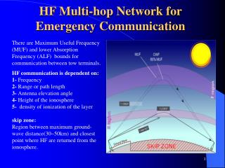
Target Failure Model • Network failure model: • Transient failures (e.g., message omissions) • Persistent failures (e.g., component crashes) • Real-time communication perspective: • Negligible bit-error rate with optical technology • Congestion-induced loss avoidance by resource reservation • Greater impact of a single component failure • Reliability of data network paths: • Less than 25 days of MTTF • More than 60% of failures last 10 minutes ~ several hours Much lower reliability than that of PSTN paths
Persistent Failure Recovery • Physical-layer techniques: • Protection switching • Self-healing approach • Advantages: • Hit-less or fast recovery • Transparency • Need of upper-layer techniques: • Inability of dealing with IP-router failures • Heterogeneity of underlying mediums • Inability of supporting application-specific fault-tolerance requirements (e.g., in multicast services)
Upper-Layer Techniques • Failure masking approach: • For applications that can’t not tolerate any message loss, e.g., multi-copy transmission with error coding • Failure detection & recoveryapproach: • For applications that can tolerate some message losses during failure recovery, e.g., on-the-fly channel rerouting • Shortcomings of on-the-fly rerouting: • No guarantees on successful recovery • Long recovery delay • High control traffic overhead • Our goal: • Fast and guaranteed failure recovery with low cost
Our Approach • Ideas: • Advance resource reservation for failure recovery (called “spare resources”) • Advance (off-line) recovery-route selection • Adependablereal-timeconnection = primary+ backup channels backup paths should be disjoint with its primary path. • Issues: • Negotiation on dependability QoS parameters • Backup path selection and spare resource allocation • Channel failure detection • Run-time failurerecovery • Resource reconfiguration after recovery
Outline of Remaining Talk • Dependability QoS parameters • Backup channel establishment • Failure detection • Run-time failure recovery • Other issues • Summary and conclusions
Dependability QoS Parameters • Probability of fast and guaranteed recovery,Pr • Markov modeling Time-varying Approximation by combinatorial reliability modeling • Negotiation between network and applications • Service-disruption time bound, G • Not negotiable • Implication: • The probability that a dependable connection will suffer from a disruption longer than G is at most Pr. • Reference: [IEEE TOC’98]
Setting Up Backup Channels • Overhead of backup channel: • No bandwidth/buffer consumption before activation • Spare resource reservation: • Can be utilized by best-effort traffic in failure-free situations, but not by real-time traffic. Reduction of network capacity to accommodate more real-time connections. • Techniques for overhead reduction: • Spare-resource sharing(backup multiplexing) • Adaptive resource control in failure-free situations
Deterministic Resource Sharing • Failure hypothesis: • The type and max number of failures are predetermined (e.g., single link failure model). • Basic procedure: • Calculate the exact amount of spare resources needed to handle all possible failures under the assumed failure model. Resource aggregation • Route optimization: • Selecting primary and backup routes so as to minimize spare resources
Limitations of Deterministic Sharing • Restricted failure hypothesis: • Same fault-tolerance capability to all connections • Limited applicability: • Applicable when resources are exchangeable among connection e.g., when bandwidth is the only resource under consideration • Centralized optimization: • High computational complexity • Adequate to static flow networks Unsuitable for large-scale, heterogeneous, dynamic networks.
Probabilistic Backup Multiplexing • Failure hypothesis: • Each network component fails with a certain probability. • Basic procedure: • If any two backup channels are not likely to be activated simultaneously, they are not accounted for in each other’s channel admission test. Channel admission by overbooking • Applicable to any real-time communication scheme • Distributed hop-by-hop spare resource calculation • Per-connection fault-tolerance control: • Use a different multiplexing degree for each connection in determining if two backups will be multiplexed or not.
Performance Evaluation • Simulation networks: • Random topologies, regular topologies (average degree 4) • Efficiency of backup multiplexing: • The overhead of backup channel is 110~150% of primary channels without multiplexing vs. 30~50% with multiplexing,for single component failure tolerance. • Means that 20~35% network capacity are reserved for backups,or dedicated to best-effort services in a failure-free situation. • Reference: [SIGCOMM’97]
Backup Route Selection • Premise: • Separation of backup route selection from backup multiplexing mechanism, i.e., spare resources are computed from given routing results. • Use existing routing methods for primary channels. • Goal: • Minimize the amount of spare resources while guaranteeing the fault-tolerance level required (NP-complete) • Two-stage approach: 1. Quick initial routing with greedy heuristics 2. Periodic/triggered route reconfiguration
Two-Stage Routing • Greedy routing: • Shortest-path routing with some link-cost metrics, for example, • f1 = 1 ( minimum hop routing ) • f2= total bandwidth reserved at the link • f3 = incremental spare bandwidth if the backup is routed over the link • Route reconfiguration: • Addition/departure of connectionsmakes already-routed backups inefficient in terms of spare resource requirements • Backup reconfiguration won’t cause actual service disruptions. • Reference: [RTSS’97]
Primary Channel Setup Backup Channel Setup Normal Operation Failure Reporting & Channel Switching Failure Detection Overview of Failure Recovery
Failure Detection • Origins of network failures: • Maintenance • Power outage • Fiber cut • Hardware errors • Software errors • Congestion • Malicious attacks • Failure-diagnosis vs. fail-over
What Failures to Detect and How? • Channel failure: • When a real-time channel experiences persistent message losses, it is said to suffer from “channel failure”. • Or, if the rate of correct message delivery within a certain time interval < a channel-specific threshold • Physical-/Data link-layer support: • Hop-by-hop packet filtering • Behavior-based channel failure detection: • Neighbor detection method • End-to-end detection method
Two Detection Methods • Neighbor method: • Periodic exchange of node heartbeatsbetween neighbor nodes • Neighbor nodes declare the failures of channels on a component, if they do not receive heartbeats from the component for a certain period. • End-to-end method: • Channel source node injects channel heartbeats between data messages. • Channel destination node detects a channel failure by monitoring message reception .
Experimental Evaluation • Strength & limitation of end-to-end detection • Perfect failure detection coverage • Long detection latency • Unable to locate the source of failure • Strength & limitation of neighbor detection • Short detection latency • Potentially imperfect detection coverage • Experimental goal • Evaluate the detection efficiencyin terms of both failure detection coverage and latency by fault-injection experiments.
Failure Detection Latency real-time message reception heartbeat reception heartbeat miss latency (neighbor) fault injection latency (end-to-end)
Experimental Setup • Hardware platform: • Three network nodes are connected by optical fiber point-to-point links. • Software: • Real-time channel protocol suite developed in RTCL, U of M. • Workload: • Two-hop real-time channels and background traffic • Fault-injection tool: • DOCTOR
Testbed Configuration NI NP AP HMON Node 1 Ethernet Data Network NI NP AP HMON Node 2 Host NI NP AP HMON Node 3 VME bus
Fault Injection • DOCTOR,an integrated fault-injection tool set: • Software-implemented fault injector • Hardware-aided data monitor (HMON) • Fault-selection tool • Specifications of injected faults: • Transient faults into NP of Node 2 at OS task scheduler, clock service, network adapter driver, and real-time channel protocol. • Memory faults, CPU faults, communication faults. • Reference: [IPDS’95]
Detection Scheme Implementation • Heartbeat generation: • By a periodic task • Heartbeat protocol: • Simple exchange of ‘I am alive’ messages • Heartbeat transmission path: • In end-to-end detection, heartbeats are transmitted as real-time messages of the corresponding channel. • In neighbor detection, heartbeats can be (option 1) transmitted as best-effortmessages, (option 2) transmitted as real-timemessages.
Experimental Results • Impacts of implementation: • Transmitting node heartbeats as real-time messages greatly enhances the detection coverage of the neighbor method. Nearly 100% detection coverage. • Workload dependency: • The performance of detection schemes is insensitive to workloads (i.e., traffic load or # of channels) and is not prone to false alarms. • Reference: [FTCS’97] [IEEE TPDS’99]
Handling of Detected Failures 1. Failure reporting: • Implicit reporting (e.g., by link-state maintenance) • Explicit reporting • What, where, and how (path) to report 2. Channel switching: • Backup activation • Traffic redirection • On-the-fly rerouting 3. Resource reconfiguration: • Closure or repair of faulty channels • Backup re-establishment or migration
Failure report Primary channel Backup channel Destination Source Activation msg Failure Reporting & Channel Switching • Time-bounded/robust failure handling • Two-way signaling • Special-type real-time channels for time-critical control message transmission (e.g., failure reports and backup activation message) --- out-of-band signaling
Resource Reconfiguration • Closure of failed channels: • Explicit or implicit closure (‘soft state’) • Dependability maintenance: • Re-establishing failed or activated backups • Allocating more spare resources or re-routing some backups • Dependability degradation: (in case of resource shortage) • Option 1: tearing down backups of some connections • Option 2: gracefully degrading dependability QoS • Option 3: degrading performance QoS of backups • Back to normal: • When failed components are repaired
Other Issues • Extension to multicast services: • Source-based tree case, shared tree case • Support for elastic QoS control schemes: • Network-triggered QoS renegotiation (e.g., ABR) • Application-triggered QoS renegotiation (e.g., RCBR) • On-going research: • Supporting hierarchical network architectures • Supporting differentiated services • Multi-layer fault-tolerance • Detection/tolerance of malicious attack
Conclusion • Salient features of the proposed scheme: • Unified method for dependable unicast/multicast QoS communication • Per-connection (or per-class) dependability QoS control • Fast (time-bounded) failure recovery • Robust/distributed failure handling • Low fault-tolerance overhead • Design philosophy: • Pre-planned failure recovery • Client-specific dependability support • Independence of the underlying technology • Reference: [IEEE Network ‘98]