Download
1 / 30
300 likes | 323 Views
Advanced project overview, criteria, block diagram, component selection rationale, schematic, PCB layout, software status, project timeline.

E N D
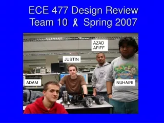
ECE 477 Design Review Team 10 Spring 2007 AZAD AFIFF JUSTIN ADAM NUHAIRI
Outline • Project overview • Project-specific success criteria • Block diagram • Component selection rationale • Packaging design • Schematic and theory of operation • PCB layout • Software design/development status • Project completion timeline • Questions / discussion
Project Overview: Hazard Rover • Remote-controlled tank with a robotic arm • User controls tank and receives status information from a control website through wi-fi interface • Wireless webcam streams video back to control website • Capabilities: • Obstacle detection – stop tank when detected • Light sensor/LED headlight • Camera tilt movement • Model of a tank to be used in a hazardous or polluted area
Project-Specific Success Criteria • An ability to control the speed and direction of the vehicle (forward/backward). • An ability to display system status (battery life, stopped/running) on an embedded web page. • An ability to sense obstacles and stop the vehicle if it is near an obstacle. • An ability to control the position of a robotic arm on the vehicle. • An ability to sense ambient light and turn on a bright LED if there is not enough light.
Block Diagram WiFi Enabled Personal Computer Vehicle Lighting Unit Camera movement servo motor (tilt) LED Headlight Light Sensor Wireless Webcam Wireless Bridge 1 1 Built-in Ethernet Interface “PWM” GPIO ATD Microcontroller 2 ATD GPIO “PWM” GPIO “PWM” 3 2 1 2 1 GPIO Obstacle Sensors DC-DC Converter DC Motor Driver DC Motor Control DC Motor Control X2 Tank Drive motor Tank steering motor Robotic Arm (DC motor) Voltage Regulator Battery To all components (5V) X3
Component Selection Rationale • 1. Microcontroller • Freescale MC9S12NE64 • Built-in ethernet interface • Has more I/O pins than project requires • 2. Battery • 8.4V NiMH Battery Pack • 4500 mAh, estimated battery life of ~2 hours before recharge
Component Selection Rationale • 3. Voltage Regulator (8.4V to 5V) • Fairchild KA78T05 Positive Voltage Regulator • All components except microcontroller can run on 5V • Capable of providing 5A, ~3 motors • 4. Voltage Regulator (5V to 3.3V) • Toshiba TA48033F Voltage Regulator • DC-DC step voltage for microcontroller
Component Selection Rationale • 5. Light Sensor • Jameco CDS Photocell 202391 • Provides variable resistance 1K-1M ohms • 6. LED Cluster • SunLED XK4MDW62 LED Cluster • Provides bright light off of 5V • 7. Camera Tilt Servo Motor • HS-422 Servo motor with “C” bracket attachment for tilt capability • Runs off 5V
Component Selection Rationale • 8. DC Motor Control • Fairchild FAN8082 Motor Driver • Runs off 5V • Drives tank steering motors as well as all robotic arm motors. • 9. Drive Motor Control • Tecel D200 High Power H-Bridge Driver • Runs off 5V, capable of driving the motor • Noisy component – on separate board
Component Selection Rationale • 10. Wireless Bridge • D-Link Wireless Bridge DWL-G820 • Instantly compatible with Ethernet-enabled microcontroller • 11. Wireless Webcam • D-Link Wireless Webcam DCS-G900 • Instantly capable of broadcasting live video feed to the web
Component Selection Rationale • 12. Robotic Arm • Jameco Robotic Arm Trainer Kit • 5 degrees of freedom, controlled by servo motors • 13. Obstacle Detection • Sharp GP2Y0A02YK Infrared Sensor • Provides analog signal 0-5V
Packaging Design Wireless Camera LED Light Sensor PCB Board Wireless Bridge Battery 9“ 15 “ 4“ Front Distance Sensor 4“ Rear Distance Sensor 20 “ 5 “
Schematic/Theory of Operation • Microcontroller
Distance Sensor • The output voltage is a function of distance from the obstacle
Light Sensor • The output voltage is a function of amount of ambient light present
Power Supply • The 8.4V supply powers all motor drivers: FAN8082 and Tecel D200 • The 5V supply powers all other components except for the microcontroller • The 3.3V supply powers the microcontroller
Ethernet Interface • Built in magnetic filter
FAN 8082 • It drives DC motors and steering motor
Wireless Camera • It operates independently of the microcontroller
Motor Drivers: FAN8082 • Left corner of the board • Motor drivers placed together to group noise production
Power Supply and Decoupling capacitors • The two voltage regulators supply the three voltages necessary to run the circuit: 8.4V, 5V, 3.3V • Opposite corner from the microcontroller
Headers • Headers for components off the board • The Tecel 200 has separate board
Software Design/Development Status • Two parts • User interface: Using C# on Visual Studio. • Controller: Keyboard and mouse • Status display: Battery life, stop, direction • UDP • Microcontroller • Using subset of C on CodeWarrior • Using OpenTCP stack for webserver • Polling loop • PWM, ATD, SCI, EPHY
Software Design/Development Status Start/Reset Read light sensor Initialization Dark? LEDs on Y N Get flags Read Front Distance Drive Forward/reverse Y Turn Close? STOP N Y Arm Y Move Arm N N Read Rear Distance Pan/Tilt Y Move camera Close? STOP N Y N