Download

1 / 16
160 likes | 185 Views
This research project aims to detect and locate pores larger than 1mm diameter inside small bores, which can cause leakage and other problems. The project includes background investigation, preliminary study, system integration, and image processing and porosity analysis.

E N D
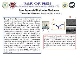
NSF Engineering Research Center forReconfigurable Manufacturing Systems Pore Detection in Small Diameter Bores The University of Michigan, Ann Arbor
Introduction • Pores above 500 micron inside small bores may cause leakage and other problem • Specifications: • Dimension: Φ 5-15 mm L 100-150 mm ( May be stepped and discontinuous) • Material: Aluminum • Pore Size: Φ < 1mm • Surface: Glossy 100-150 mm Φ15mm Φ5mm
In-line inspection of the inner surface of small bores of power train parts Detect and locate pores lager than 1mm diameter inside a small bore Project goals
Stage 1. Background investigation (April, 2007 ) Stage 2. Preliminary study (May, 2007) Stage 3. System integration (June, 2007) Stage 4. Image processing and porosity analysis (July-Now, 2007) Progress
Sight Pipe System CCD Z rotary stage X Y motion stage Sight Pipe Sample Side and top view of the system
Scanning results “Paper Bore” image 13 mm Diameter Real Bore image Theshadow lines appears
Scanning result after alignment Large intensity variance Before alignment small intensity variance After alignment
Alignment of Camera and motion stage • Step1- Focus the camera onto a target point at a close distance and center the target using linear adjustments. • Step2- Use motion stage to move the camera to the further distance and center the target using angular adjustments. Step3- Repeat steps 1 and 2 until the targets are centered in the same position.
Aligning the Bore axis • Step1-Focus on front of the bore and find the center of the circular opening. • Step2-Focus on the back of the bore and find the center of a circular ring. • Step3-Align angular and linear positioning of the bore until the two reference circles are centered with the camera.
Straightness and angular tolerance for aligning the Bore • The bore must be properly aligned to provide a low intensity variance for the unwrapping zone. • Straightness should be within ~0.18 mm in each direction • Angular error should be within ~670 arcsecs
Software interface improvement User-Friendly interface Well organized program with clear comments Porosity analysis using Labview Detect pores with different size Indicate the location of the pores Filter the pores as needed (By size, location and so on) Provide statistic table Redesign mounting structure for the sight pipe system to add one degree of freedom in vertical direction Current Work
Sight Pipe + IMAQ image processing: Finding center polar unwrapping stitching Motion control:Magnification = real width of line / pixel width of line*Pixel size Total time of Scan = scanning distance/ motion velocity Motion velocity= Width of sampling zone*Pixel size*Magnification / Sampling period Finding the Pore: Threshold Particle Filter Particle Analysis Some Algorithms
A background correction threshold is applied to the entire image. Background correction breaks the image up into smaller regions and searches for the darkest areas in each image. The particles are then put through a particle filter based on the major axis of the best fit ellipse. The image saved with particle information are loaded into a screen that allows the user to easily see the pores and their location based on the filter been chosen. Image Processing
MINI CCD updating 51 degree field of view with normal lens Inside view of a bore ( 13 & 30 mm diameter)
Fiber illumination for the MINI CCD Fiber MINI CCD
Optimize the pore detection algorithms Improve the mounting structure of the sight pipe system Increasing the optical magnification to get higher resolution Upgrading the CCD and DAQ device for higher speed if necessary Continue the Mini CCD research Next Steps