Download
1 / 1
10 likes | 93 Views
Explore the advanced detection capabilities of active dipole antennas for cosmic rays in the CODALEMA experiment at Nançay Observatory. Discover the benefits and drawbacks of dipole antennas compared to log-periodic antennas, and learn about designing wide-band antennas with low-noise preamplifiers utilizing ASIC technology.

E N D
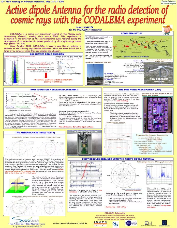
dipoles 600 m 450 m 10th PISA meeting on Advanced Detectors, May 21-27 2006 The ‘Heart’ of the active dipole antenna Antenna gain fot the highest frequencies (50 to 100MHz), in H-plane and E-plane Antenna gain fot the lowest frequencies up to 30MHz, in H-plane and E-plane The measured LNA bandwith The measured LNA input noise Radio spectrum measured at Nançay radio observatory The Layout of the ASIC designed in the AMS BiCMOS 0.8 technology 100 kHz 100 MHz 100 MHz 10 kHz 1nV/Hz -3dB Bandwidth trigger :4 particles detector in coincidences FWHM Amplitude NEW CODALEMA ANTENNA 2Ca Ra/2(f) La/2 IN+ OUT+ Ce ~ ~ Ui G Vout=G Ui Ua 2Ca La/2 Ra/2(f) OUT- IN- Low noise preamplifier(LNA) Antenna voltage Antenna impedance Za Simplified electrical model of a dipole antenna 12 km 5 km H-plane E-plane Cosmic Rays pulses Antenna length = 1.21m Height=1.20m FLOOR Zenith Zenith floor Active dipole Antenna for the radio detection of cosmic rays with the CODALEMA experiment Didier CHARRIER for the CODALEMA Collaboration CODALEMA SETUP CODALEMA is a cosmic ray experiment located at the Nançay radio Observatory (France), running since march 2003. This experiment is dedicated to the detection of the electromagnetic pulse radiated during the development of an extensive air shower produced by ultra high energy cosmic rays (above 1017 eV). Since October 2005, CODALEMA is using a new kind of antenna in addition to the existing Log-Periodic antennas. They are more fitted for a large array detector since they are simpler and cheaper. The CODALEMA experiment is made of a line of 7 log-periodic antennas. 7 active dipole antennas were added on a perpendicular axes in October 2005. The 2 lines are arranged on a cross. The air shower direction is calculated by triangulation. The air shower profile is measured in two directions by the amplitude recorded on each antenna. Rem : All the log-periodic antennas will be replaced soon by active dipole antennas. AIR SHOWER RADIO EMISSION Example of a simulated Cosmic ray shower at 1019 eV Calculated electric fields for 3 different impact parameters b in a vertical shower configuration (Excess of negative charge Model) The new active dipole in operation since october 2005 Dipole advantage -Easy to built -Very easy to carry and to install -Very wide bandwidth & low cut off frequency (10kHz –100 MHz) -Cheap Dipole drawbacks -Require a low noise preamplifier - only 1 polarisation measured Log-Periodic antennas used since 2003 The knowledge of the amplitude leads to the Energy of the primary cosmic ray The Knowledge of the FHWM leads to the impact parameter (b) with a FHWM ranging from 10ns (b0m) to 1s (b3 km) • Log advantage • -Very sensitive, sky noise limited • -Measure Electric field in all directions with only one analog channel • Log drawbacks • -Difficult to built • -Difficult to carry and to install (height=8m) The antenna must have a WIDE BANDWIDTH (100kHz to 100MHz). HOW TO DESIGN A WIDE BAND ANTENNA ? THE LOW NOISE PREAMPLIFIER (LNA) The antenna preamplifier must be a capacitive input impedance one with a wide band and a low noise. It must be placed as close as possible to the dipole antenna. To fulfill these constraints it has been designed with the ASIC technology. For f<<f0 (short dipole), Za Ca Consequently, the relationship between the preamplifier input voltage(Ui) and the antenna voltage(Ua) is: Ui/Ua = Ca / (Ca+Ce) This transfer function is independent of the frequency since it’s a capacitive attenuator. We need Ca as great as possible to lower the attenuation. Since a low noise is required from the lowest frequencies and the antenna impedance is inversely proportional to the frequency, a MOS transistor has been chosen as input one due to its absence of current noise. How to increase Ca without decreasing f0 ? Ca is depending only of the dipole geometry: The antenna length(L) and diameter(D): Ca 0L / 2(ln(L/D)-1) , with 0=410-7 The maximum antenna length is given by the resonance condition: f0 C/2L >> 100MHz , with C=8.854 10-12 Fm-1 Thus, the only way to increase Ca is to increase the antenna diameter. The solution is a fat active dipole antenna The flicker noise is reduced by choosing a P channel. The input thermal noise is inversely proportional to the transconductance of the transistor. This is why the input stage is using a wide transistor • A simplified electrical model of the dipole antenna is composed of an a voltage source (Ua) and an antenna impedance (Za). Ua is proportional to the antenna length(L) and to the amplitude of the received Electric field. The antenna impedance is equivalent to a RLC resonant circuit. The resistance is the sum of a radiation(Ra) and a loss(Rloss) resistance. The value of Ra which is 75(thin dipole in free space) at the resonant frequency is decreasing to the power 4 with the frequency. The loss resistance is a few ohm. The resonant frequency(f0) is depending on the antenna length(L) which is modelised by the product of La by Ca: f0 = C/2L = 1/ (2LaCa). • The input impedance of the LNA is equivalent to a capacitance(Ce) and the value of its voltage gain is G. THE ANTENNA GAIN (DIRECTIVITY) The preamplifier Measured Characteristics Asic input noise: High cut off frequency: Low cut off frequency: Input capacitance: Rise & fall time: input dynamic: Voltage gain: Consumption: 1.3 nV/Hz @ 1MHz 800 pV/Hz @ 100MHz 240MHz Adjustable from 10kHz to 2MHz 10pF 1.5ns 24mV pick to pick Digitally adjustable from 30dB to 36.7dB 48mA under 5.5V Zenith Zenith floor FIRST RESULTS OBTAINED WITH THE ACTIVE DIPOLE ANTENNA The dipole antenna gain is simulated with a software (EZNEC). The conditions of simulation are an antenna above a perfect ground floor. The two figures above represents the total gain deviation versus the elevation angle for many frequencies from 1MHz to 30MHz and for two perpendicular planes called E and H-plane. The gain display on those figures is not a power but a normalized voltage since it’s an active antenna. For all the frequencies ranging from 1MHz or well below, up to 30MHz, the antenna_height/wavelength ratio is small(<1/10). This is the reason why the antenna gain can be considered as a constant value. The voltage half beam width is equal to 120° in the H-plane and 90° in the E-plane. Short waves FM band The two figures below represents the same as above but for frequencies above 30MHz. the antenna_height/wavelength ratio become greater, so a destructing interferences appears with the frequency because of the delay between the incident wave and the reflected (by the perfect ground floor) one. It is well visible for the 100MHz frequency where the zenith gain is half the low frequency gain. This could be enhanced by lower the antenna 1MHz 150MHz This figure shows the measurement of 3 spectra from 1MHz to 150MHz. The green curve is the spectrum analyzer noise, the black one is the electronics noise (antenna disconnected from the preamplifier). The blue one is the antenna spectrum measurement, which is getting out electronics noise from 45MHz to 150MHz. This extra noise is the sky noise contribution. Detection of a cosmic ray air shower in time coincidence by a line of 7 active dipoles. The graphs are the voltage measured (Volt) versus time (s). Cosmic ray pulses, appearing as oscillating features due to the 37-70MHz filtering, are clearly visible. Their arrival time on each antenna depends on the location of them. Oscillating structures seen on the sides are artifacts due to the offline numerical processing. • Projection on the ground plane of Cosmic rays arrival directions (angular difference < 5°) • -The circles indicate directions reconstructed from antenna signals (Log + dipole) • -The crosses correspond to directions given by the scintillators • Counting rate : 1.21 evt/day CODALEMA Collaboration SUBATECH, Université de Nantes/IN2P3-CNRS/École des Mines de Nantes Station de Radio Astronomie de Nançay , LESIA, Observatoire de Paris-Meudon LAL Orsay, Université de Paris-Sud, LPSC Grenoble , ESEO Angers, didier.charrier@subatech.in2p3.fr 4 rue A. Kastler 44307 Nantes France http://www-subatech.in2p3.fr