Download
1 / 29
290 likes | 410 Views
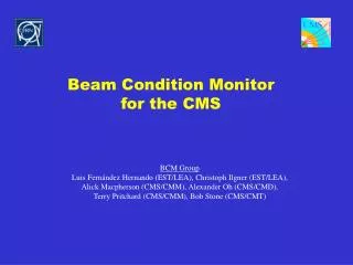
The ATLAS Beam Conditions Monitor. Marko Miku ž University of Ljubljana & Jo ž ef Stefan Institute IEEE NSS ’07 N31-7 Hawaii, October 31, 2007. The ATLAS BCM collaboration. CERN D. Dabos, H. Pernegger, P. Weilhammer Fotec & Univ. Wiener Neustadt E. Griesmayer, H. Frais-Kölbl, M. Niegl

E N D
The ATLAS Beam Conditions Monitor Marko Mikuž University of Ljubljana & Jožef Stefan Institute IEEE NSS’07 N31-7 Hawaii, October 31, 2007
The ATLAS BCM collaboration • CERN • D. Dabos, H. Pernegger, P. Weilhammer • Fotec & Univ. Wiener Neustadt • E. Griesmayer, H. Frais-Kölbl, M. Niegl • JSI & Univ. Ljubljana • V. Cindro, I. Dolenc, A. Gorišek, G.Kramberger, B. Maček, I. Mandić, E. Margan, M. Zavrtanik, M. Mikuž • OSU, Columbus • H. Kagan, S. Smith • Univ. Toronto • M. Cadabeschi, D. Tardif, W. Trischuk • ~20 people from 5 institutes ATLAS BCM (M.Mikuž, Ljubljana)
Aim of the ATLAS BCM • Goal of the BCM detector system inside the ATLAS Inner Detector: • Monitor instantaneous background rate and collision rate during normal running • Measure background rate close to vertex • Compare to rate of collisions and provide basic bunch-by-bunch luminosity measurement • Protection in case of larger beam losses • Detect early signs of beam instabilities (e.g. wrong magnet settings, trips,…) • Issue warning and alarm signals for equipment protection • Input to ATLAS Detector Safety system and LHC beam abort ATLAS BCM (M.Mikuž, Ljubljana)
Timing of background vs. interactions Time difference • Distinguish collisions from background through time-of-flight measurement with detectors at either side of the IP • Is measured for every bunch crossing (25ns) • Requires fast and radiation hard detector + electronics ( rise time ~ 1ns, pulse width ~ 3ns, baseline restoration < 10ns) • Out of collision time hits signatures of beam anomalies BCM Side A - Side C Interactions: Dt = 0, 25, … nsUpstream background: Dt = 2z/c = 12ns ATLAS BCM (M.Mikuž, Ljubljana)
The Beam Conditions Monitor 38 cm 183cm • 4 BCM stations on each side of the Pixel detector • Mounted on Pixel support structure at z = +/- 183.8 cm and r = 5.5 cm • Each station: 1 cm2 detector element + front-end analogue readout ATLAS BCM (M.Mikuž, Ljubljana)
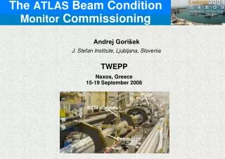
The BCM is installed in ATLAS • BCM installed on Pixel detector, lowered into ATLAS pit in June 2007 ATLAS BCM (M.Mikuž, Ljubljana)
The BCM Module • Sensors are poly-crystalline CVD diamonds • Developed by RD42 and Element Six Ltd • Radiation hard • Shown to withstand > 1015 p/cm2 • Fast & short signal (FWHM~2ns, rise time<1ns) • Large charge carrier drift velocity (107 cm/s)(operates at high drift field ~2 V/m) • Very low leakage current after irradiation • Does not require detector cooling 2 diamonds each with: Thickness 500 m CCD @1V/m ~ 200m Size: 10 x 10 mm2 Contact size: 8 x 8 mm2 BCM operation: 2 V/m ATLAS BCM (M.Mikuž, Ljubljana)
Front-end readout: RF amplifier • 2-stage amplification of ionization current pulse • RF amplifier, no feed-back • Parameters • Bandwidth 500 MHz (1st stage) • Amplification ~40 dB • Radiation hard to ~1015 n/cm2 • Tested at Ljubljana TRIGA reactor and CERN PS • Find gain reduction of 20% after 5x10¹⁴ n/cm2 plus 5x10¹⁴ p/cm2 at constant noise ATLAS BCM (M.Mikuž, Ljubljana)
BCM system overview Inside Pixel Package At PP2 (~1st muon chamber) Counting room USA15 ~1 krad TOT “digitization” ~30 Mrad detector ATLAS BCM (M.Mikuž, Ljubljana)
Functional tests of BCM chain • BCM modules and performance of the signal processing chain have been tested in several lab tests and test beams • We currently use beam tests to commission the readout electronics using three spare modules • The next slides will show an overview of the tests done: • Module tests during production • Analogue signal response during beam tests • Performance after analogue-to-digital conversion and optical link • Efficiency & Noise • Timing resolution ATLAS BCM (M.Mikuž, Ljubljana)
Module tests • Diamonds • IV curve & CCD measurements before assembly to modules • Use 90Sr source test setup to characterize each module • Measure signal distribution and noise in HV scan from -1000V to +1000V • Done before and after burn-in (80°C@12hrs) and thermal cycling (10 cycles -20 to +40°C) while modules are operated • Measure on modules a most probable SNR = (7.3 ± 0.56) :1 for 90° impact • Meets our requirement of 10:1 in final configuration at 45° ( x √2) Noise rms ~330 V Smp ~ 2.7mV 200 MHz BWL ATLAS BCM (M.Mikuž, Ljubljana)
Test beam (CERN SPS) • Test BCM modules in high energy pion beam at CERN SPS • Goal: • Evaluate analogue signals • Test NINO time-over-threshold (TOT) conversion and opto-link • Measure efficiency, noise rate and timing resolution • Test V1.0 of FPGA readout board • Setup: • Telescope with 5 scintillators and 2x2mm2 trigger area, BCM modules moved across beam • BCM stations connected via 16 m coax cable to Ortec 300 MHz amplifier for analogue measurements and VME 2 Gs/s ADC • BCM stations connected via 16 m coaxial cable to NINO board + opto transmitter + fibre + opto receiver going to VME readout and FPGA readout ATLAS BCM (M.Mikuž, Ljubljana)
Signal uniformity & time resolution NINO Time res ~ 490ps No tails ! • Time difference of NINO outputs between 2 BCM stations • NINO threshold fixed to 200 mV • Easily meets requirement of 1 ns • Efficiency versus beam position • Analogue signal > 150 ADC counts • Scans in steps of 1x1 mm2 • Exhibits very efficient and uniform response over active area Efficiency ATLAS BCM (M.Mikuž, Ljubljana)
Time resolution NINO Time res ~ 490ps No tails ! • Time difference between 2 BCM stations • Two measurement sets: • Offline analysis of analogue signals assuming a start time at 50% amplitude (“constant-fraction-discriminator”) • Time resolution of NINO output with fixed threshold in NINO operational range (200mV) Analog Time res ~ 360ps ATLAS BCM (M.Mikuž, Ljubljana)
Efficiency and noise rate Beam blocker IN • Efficiency and noise rate measured after analogue-to-digital conversion with NINO and optical link Slope = 31mV rms noise * Muons “leaking” through beam blocker Median signal 335mV on NINO discriminator Machine development – lower muon rate * Baseline noise of NINO without input connected = 13.5mV rms • Efficiency >99% for threshold of 180mV or less • Median SNR after full signal chain ~ 11:1 ATLAS BCM (M.Mikuž, Ljubljana)
Operation in ATLAS • For operation want to maximize efficiency at minimal number of noise hits per LHC BX (25 ns) • Threshold optimized with efficiency versus noise occupancy per module and BX: • Horizontal axis is calculated from fit to previous noise vs threshold plot e.g. 180 mV threshold: Efficiency is 99% at noise occupancy of 3 x 10⁻⁸ /module/BX At low luminosity (5x1032 cm-2s-1) expect ~13% of BX’s have Side A-C coincidence ATLAS BCM (M.Mikuž, Ljubljana)
Radiation test of complete module 1014 p/cm2 non-irradiated • Radiation hardness of sensors, electronics and components verified separately up to level of 1015 cm-2 (30 MRad) • Want to assess performance of complete module • Irradiation/test of one module • Test in beam – June 07 • Irradiate to 1014 p/cm2 – July 07 • Test in beam – August 07 • Irradiate to 3x10¹⁴ p/cm2 – September 07 • Test in beam – now • Irradiate to 1015 p/cm2 – Spring 08 • Test in beam – Summer 08 • ~20 % of signal loss observed in test beam after 1014 p/cm2 • Diamonds not properly pumped – need to cover complete sensor • Loss consistent with that of samples irradiated to same fluence with neutrons – see talk N44-5 tomorrow • Expect complete signal recovery after pumping • Tests with module irradiated to 3x10¹⁴ p/cm2 ongoing ATLAS BCM (M.Mikuž, Ljubljana)
Summary • ATLAS BCM will monitor beam conditions close to the IP in ATLAS using a time-of-flight measurement • Based on pCVD diamonds readout by fast RF amplifiers to achieve very fast signal response and required radiation hardness • Rise time 1.3ns & ~2ns FWHM pulse width • We have tested the full set of BCM modules in beam tests demonstrating the required performance • Efficiency of ~99% at operational threshold with noise occupancy /module/BX <10-7 • Time resolution ~500ps • All BCM modules were installed in ATLAS together with the ATLAS Pixel detector in June 2007 ATLAS BCM (M.Mikuž, Ljubljana)
Backup slides … ATLAS BCM (M.Mikuž, Ljubljana)
LHC beam losses • E.g. wrong magnet settings or trips can lead to beam scraping on collimators • Simulations of beam orbits with wrong magnet settings near ATLAS IP (D. Bocian Accidental Beam Losses during Injection in the Interaction Region IR1 Dariusz Bocian / EST-LEA and ATLAS) • Time constants of failures (trips ,…) are often large (~ms) • If signs are detected early, the beam can be aborted ATLAS BCM (M.Mikuž, Ljubljana)
Signal optimization • Step 1: 2 Diamonds read out in parallel increase signal by factor 2, noise increases only by ~30% • Step 2: Place at 45 degrees -> 2 signal increase, no noise increase • Step 3: Adding ~200-300MHz BWL on NINO input improves SNR by 30% (timing resolution worsens by ~ 10%) • Step 4: operate at 2V/m instead of 1V/m -> increases signal by up to 50% amplitude noise RMS=0.66mV no BWL MP=3.7mV RMS=0.33mV 200MHz BWL MP=2.5mV SNR ATLAS BCM (M.Mikuž, Ljubljana)
Analogue response in test beam • Single event and signal distribution • <Signal rise time>=1.3 ns and <FWHM pulse width> = 2.1 ns • Signal and noise well separated ATLAS BCM (M.Mikuž, Ljubljana)
Number of BCM hits & coincidences 5 x 1032 2.8 x 1034 1 x 1034 • Number of BCM station hits/BCO • At low luminosity expect ~ 50% of BCO have >= 1 hit • Coincidences • Plots as # Side A * # Side C • At low luminosity expect ~13% of BCM have a coincidence No timing cut ATLAS BCM (M.Mikuž, Ljubljana)
Radiation Test results • Measure response of irradiated 1st stage after full irradiation with Si-diode and 90Sr source • Noise constant • Overall gain reduction of ~ 20% after full irradiation ATLAS BCM (M.Mikuž, Ljubljana)
LHC Beam loss scenario • Simulation by CMS: single proton lost on collimator (“TAS”) (dose [Gy]) ~ MIPs/cm2 per proton (M. Huhtinen, LHC Machine Protection WG, Oct. 2003) ATLAS BCM (M.Mikuž, Ljubljana)
Passive signal summation • Increase signal by using 2 diamonds acting as one current source (“Double diamond assembly”) • 2 independent current signals summed at input signal HV drift voltage ATLAS BCM (M.Mikuž, Ljubljana)
FPGA backend • Have developed the V1.0 signal processing code • Rocket I/O acquisition of BCM signals from optical board (2.6 GHz sampling) • Edge detection, pulse width calculation • DDR2 circular buffers • Ethernet + Client Software on PC • In-time/out-of-time coincidences • Tested in most recent beam tests with full signal chain and two BCM stations • Data analysis is ongoing • Plan second run with FPGA end October in SPS testbeam ATLAS BCM (M.Mikuž, Ljubljana)
BCM simulations • Simulations in full ATHENA framework • Average number of tracks in BCM diamonds per p-p collision: 0.375 • Surprise: half of events from decays and scattering in material • Studies of coincidences to establish FPGA algorithms ongoing Pixels Beam pipe Decays BCM ATLAS BCM (M.Mikuž, Ljubljana)
BCM simulations – movement of vertex • Explored sensitivity of BCM rates to vertex displacements • Vertex displaced to z = +10 cm • Surprise: more BCM hits on side C – secondaries dominate • dPA/dz = (-0.11 ± 0.05) m-1, effect at % level ( • dPA/dz = +0.12 m-1 for primaries only More material towards Side C Vertex at z=0 Vertex at z=+10 ATLAS BCM (M.Mikuž, Ljubljana)