1.4 INTRODUCTION TO PROGRAM SEGMENTS
1.4 INTRODUCTION TO PROGRAM SEGMENTS. A typical Assembly language program consists of at least three segments: A code segment - which contains the Assembly language instructions that perform the tasks that the program was designed to accomplish.

1.4 INTRODUCTION TO PROGRAM SEGMENTS
E N D
Presentation Transcript
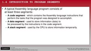
1.4 INTRODUCTION TO PROGRAM SEGMENTS • A typical Assembly language program consists ofat least three segments: • A code segment - which contains the Assembly language instructions that perform the tasks that the program was designed to accomplish. • A data segment - used to store information (data) tobe processed by the instructions in the code segment. • A stack segment - used by the CPU to store information temporarily.
1.4 INTRODUCTION TO PROGRAM SEGMENTS origin and definition of the segment • A segment is an area of memory that includes upto 64K bytes, and begins on an address evenly divisible by 16 (such an address ends in 0H) • 8085 addressed a maximum of 64K of physical memory, since it had only 16 pins for address lines. (216 = 64K) • Limitation was carried into 8088/86 design for compatibility. • In 8085 there was 64K bytes of memory for all code, data, and stack information. • In 8088/86 there can be up to 64K bytes in each category. • The code segment, data segment, and stack segment.
1.4 INTRODUCTION TO PROGRAM SEGMENTS logical address and physical address • In literature concerning 8086, there are three types of addresses mentioned frequently: • The physical address - the 20-bit address actually on the address pins of the 8086 processor, decoded by the memory interfacing circuitry. • This address can have a range of 00000H to FFFFFH. • An actual physical location in RAM or ROM within the 1 mb memory range. • The offset address - a location in a 64K-byte segment range, which can can range from 0000H to FFFFH. • The logical address - which consists of a segment value and an offset address.
1.4 INTRODUCTION TO PROGRAM SEGMENTS code segment • To execute a program, 8086 fetches the instructions (opcodes and operands) from the code segment. • The logical address of an instruction always consists of a CS (code segment) and an IP (instruction pointer), shown in CS:IP format. • The physical address for the location of the instructionis generated by shifting the CS left one hex digit, then adding it to the IP. • IP contains the offset address. • The resulting 20-bit address is called the physical address since it is put on the external physical address bus pins.
1.4 INTRODUCTION TO PROGRAM SEGMENTS code segment • Assume values in CS & IP as shown in the diagram: • The offset address contained in IP, is 95F3H. • The logical address is CS:IP, or 2500:95F3H. • The physical address will be 25000 + 95F3 = 2E5F3H
1.4 INTRODUCTION TO PROGRAM SEGMENTS code segment • Calculate the physical address of an instruction: • The microprocessor will retrieve the instruction from memory locations starting at 2E5F3.
1.4 INTRODUCTION TO PROGRAM SEGMENTS code segment • Calculate the physical address of an instruction: • Since IP can have a minimum value of 0000H and a maximum of FFFFH, the logical address range in this example is 2500:0000 to 2500:FFFF.
1.4 INTRODUCTION TO PROGRAM SEGMENTS code segment • Calculate the physical address of an instruction: • This means that the lowest memory location of the code segment above will be 25000H (25000 + 0000) and the highest memory location will be 34FFFH (25000 + FFFF).
1.4 INTRODUCTION TO PROGRAM SEGMENTS code segment • What happens if the desired instructions are located beyond these two limits? • The value of CS must be changed to access those instructions.
1.4 INTRODUCTION TO PROGRAM SEGMENTS code segment logical/physical address • In the next code segment, CS and IP hold the logical address of the instructions to be executed. • The following Assembly language instructions have been assembled (translated into machine code) and stored in memory. • The three columns show the logical address of CS:IP, the machine code stored at that address, and the corresponding Assembly language code. • The physical address is put on the address bus by the CPU to be decoded by the memory circuitry.
1.4 INTRODUCTION TO PROGRAM SEGMENTS code segment logical/physical address Instruction "MOV AL,57" has a machine code of B057. B0 is the opcode and 57 is the operand.
1.4 INTRODUCTION TO PROGRAM SEGMENTS code segment logical/physical address Instruction "MOV AL,57" has a machine code of B057. B0 is the opcode and 57 is the operand. The byte at address 1132:0100 contains B0, the opcode for movinga value into register AL. Address 1132:0101 contains the operand to be moved to AL.
1.4 INTRODUCTION TO PROGRAM SEGMENTS data segment • Assume a program to add 5 bytes of data, such as 25H, 12H, 15H, 1FH, and 2BH. • One way to add them is as follows: • In the program above, the data & code are mixed together in the instructions. • If the data changes, the code must be searched for every place it is included, and the data retyped • From this arose the idea of an area of memory strictly for data
1.4 INTRODUCTION TO PROGRAM SEGMENTS data segment • In x86 microprocessors, the area of memory set aside for data is called the data segment. • The data segment uses register DS and an offset value. • DEBUG assumes that all numbers are in hex. • No "H" suffix is required. • MASM assumes that they are in decimal. • The "H" must be included for hex data. • The next program demonstrates how data canbe stored in the data segment and the programrewritten so that it can be used for any set of data.
1.4 INTRODUCTION TO PROGRAM SEGMENTS data segment • Assume data segment offset begins at 200H. • The data is placed in memory locations: • The program can be rewritten as follows:
1.4 INTRODUCTION TO PROGRAM SEGMENTS data segment • The offset address is enclosed in brackets, which indicate that the operand represents the addressof the data and not the data itself. • If the brackets were not included, as in "MOV AL,0200", the CPU would attempt to move 200 into AL instead of the contents of offset address 200. decimal. • This program will run with any set of data. • Changing the data has no effect on the code.
1.4 INTRODUCTION TO PROGRAM SEGMENTS data segment • If the data had to be stored at a different offset address the program would have to be rewritten • A way to solve this problem is to use a register to holdthe offset address, and before each ADD, increment the register to access the next byte. • 8088/86 allows only the use of registers BX, SI, and DI as offset registers for the data segment • The term pointer is often used for a register holdingan offset address.
1.4 INTRODUCTION TO PROGRAM SEGMENTS data segment • In the following example, BX is used as a pointer: • The INC instruction adds 1 to (increments) its operand. • "INC BX" achieves the same result as "ADD BX,1“ • If the offset address where data is located is changed, only one instruction will need to be modified.
1.4 INTRODUCTION TO PROGRAM SEGMENTS data segment logical/physical address • The physical address for data is calculated using the same rules as for the code segment. • The physical address of data is calculated by shifting DS left one hex digit and adding the offset value, as shownin Examples 1-2, 1-3, and 1-4.
1.4 INTRODUCTION TO PROGRAM SEGMENTS data segment logical/physical address
1.4 INTRODUCTION TO PROGRAM SEGMENTS data segment logical/physical address
1.4 INTRODUCTION TO PROGRAM SEGMENTS little endian convention • Previous examples used 8-bit or 1-byte data. • What happens when 16-bit data is used? • The low byte goes to the low memory location and the high byte goes to the high memory address. • Memory location DS:1500 contains F3H. • Memory location DS:1501 contains 35H. • (DS:1500 = F3 DS:1501 = 35) • This convention is called little endian vs big endian. • From a Gulliver’s Travels story about how an egg shouldbe opened—from the little end, or the big end.
1.4 INTRODUCTION TO PROGRAM SEGMENTS little endian convention • In the big endian method, the high byte goes to the low address. • In the little endian method, the high byte goes to thehigh address and the low byte to the low address.
1.4 INTRODUCTION TO PROGRAM SEGMENTS little endian convention • All Intel microprocessors and many microcontrollers use the little endian convention. • Freescale (formerly Motorola) microprocessors, along with some other microcontrollers, use big endian.
1.4 INTRODUCTION TO PROGRAM SEGMENTS extra segment (ES) • ES is a segment register used as an extra data segment. • In many normal programs this segment is not used. • Use is essential for string operations.
Figure 1-3 Memory Allocation in the PC 1.4 INTRODUCTION TO PROGRAM SEGMENTS memory map of the IBM PC • The 20-bit address of 8088/86 allows 1mb (1024K bytes) of memory space with the address range 00000–FFFFF. • During the design phase of the first IBM PC, engineers had to decideon the allocation of the 1-megabyte memory space to various sectionsof the PC. • This memory allocation iscalled a memory map.
Figure 1-3 Memory Allocation in the PC 1.4 INTRODUCTION TO PROGRAM SEGMENTS memory map of the IBM PC • Of this 1 megabyte, 640K bytes from addresses 00000–9FFFFH were set aside for RAM • 128K bytes A0000H– BFFFFH were allocated for video memory • The remaining 256K bytes from C0000H–FFFFFH were set aside for ROM
1.4 INTRODUCTION TO PROGRAM SEGMENTS more about RAM • In the early 80s, most PCs came with 64K to 256K bytes of RAM, more than adequate at the time • Users had to buy memory to expand up to 640K. • Managing RAM is left to Windows because... • The amount of memory used by Windows varies. • Different computers have different amounts of RAM. • Memory needs of application packages vary. • For this reason, we do not assign any values for the CS, DS, and SS registers. • Such an assignment means specifying an exact physical address in the range 00000–9FFFFH, and this is beyond the knowledge of the user.
1.4 INTRODUCTION TO PROGRAM SEGMENTS video RAM • From A0000H to BFFFFH is set aside for video • The amount used and the location vary dependingon the video board installed on the PC
1.4 INTRODUCTION TO PROGRAM SEGMENTS more about ROM • C0000H to FFFFFH is set aside for ROM. • Not all the memory in this range is used by the PC's ROM. • 64K bytes from location F0000H–FFFFFH areused by BIOS (basic input/output system) ROM. • Some of the remaining space is used by various adapter cards (such as the network card), and the rest is free. • The 640K bytes from 00000 to 9FFFFH is referredto as conventional memory. • The 384K bytes from A0000H to FFFFFH are calledthe UMB (upper memory block).
1.4 INTRODUCTION TO PROGRAM SEGMENTS function of BIOS ROM • There must be some permanent (nonvolatile) memory to hold the programs telling the CPUwhat to do when the power is turned on • This collection of programs is referred to as BIOS. • BIOS stands for basic input-output system. • It contains programs to test RAM and othercomponents connected to the CPU. • It also contains programs that allow Windows to communicate with peripheral devices. • The BIOS tests devices connected to the PC whenthe computer is turned on and to report any errors.
1.5 THE STACK what is a stack? why is it needed? • The stack is a section of read/write memory (RAM) used by the CPU to store information temporarily. • The CPU needs this storage area since there areonly a limited number of registers. • There must be some place for the CPU to storeinformation safely and temporarily. • The main disadvantage of the stack is access time. • Since the stack is in RAM, it takes much longer toaccess compared to the access time of registers. • Some very powerful (expensive) computers do not have a stack. • The CPU has a large number of registers to work with.
1.5 THE STACK how stacks are accessed • The stack is a section of RAM, so there must be registers inside the CPU to point to it. • The SS (stack segment) register. • The SP (stack pointer) register. • These registers must be loaded before anyinstructions accessing the stack are used. • Every register inside the x86 can be stored in the stack, and brought back into the CPU from thestack memory, except segment registers and SP. • Storing a CPU register in the stack is called a push. • Loading the contents of the stack into the CPU registeris called a pop.
1.5 THE STACK how stacks are accessed • The x86 stack pointer register (SP) points at the current memory location used as the top of the stack. • As data is pushed onto the stack it is decremented. • As data is poppedoff the stack into the CPU, it is incremented. • When an instruction pushes or pops a general-purpose register, it must be the entire 16-bit register. • One must code "PUSH AX". • There are no instructions such as "PUSH AL" or "PUSH AH".
1.5 THE STACK how stacks are accessed • The SP is decremented after the push is to make sure the stack is growing downward from upper addresses to lower addresses. • The opposite of the IP. (instruction pointer) • To ensure the code section & stack section of the program never write over each other, they arelocated at opposite ends of the RAM set asidefor the program. • They grow toward each other but must not meet. • If they meet, the program will crash.
1.5 THE STACK pushing onto the stack • As each PUSH is executed, the register contents are saved on the stack and SP is decremented by 2.
1.5 THE STACK pushing onto the stack • For every byte of data saved on the stack, SP is decremented once. Since the pushis saving the contents of a16-bit register,it decrements twice.
1.5 THE STACK pushing onto the stack • In the x86, the lower byte is always stored in the memory location with the lower address. 24H, the content of AH, is savedin the memory location with the address 1235. AL is stored in location 1234.
While the data actually remains in memory, it is not accessible, since the stack pointer, SP is beyond that point. 1.5 THE STACK popping the stack • With every pop, the top 2 bytes of the stack are copied to the x86 CPU register specified by the instruction & the stack pointer is incremented twice.
1.5 THE STACK logical vs physical stack address • The exact physical location of the stack depends on the value of the stack segment (SS) register andSP, the stack pointer. • To compute physical addresses for the stack, shiftleft SS, then add offset SP, the stack pointer register. • Windows assigns values for the SP and SS.
1.5 THE STACKa few more words about x86 segments • Can a single physical address belong to many different logical addresses? • Observe the physical address value of 15020H. • Many possible logical addresses represent this singlephysical address: • An illustration of the dynamic behavior of the segment and offset concept in the 8086 CPU.
1.5 THE STACKa few more words about x86 segments • When adding the offset to the shifted segment register results in an address beyond the maximum allowed range of FFFFFH, wrap-around will occur.
1.5 THE STACKoverlapping • In calculating the physical address, it is possible that two segments can overlap.
1.6 FLAG REGISTER • Many Assembly language instructions alter flag register bits & some instructions function differently based on the information in the flag register. • The flag register is a 16-bit register sometimes referred to as the status register. • Although 16 bits wide, only some of the bits are used. • The rest are either undefined or reserved by Intel.
1.6 FLAG REGISTER • Six flags, called conditional flags, indicate some condition resulting after an instruction executes. • These six are CF, PF, AF, ZF, SF, and OF. • The remaining three, often called control flags, controlthe operation of instructions before they are executed.
1.6 FLAG REGISTER bits of the flag register • Flag register bits used in x86 Assembly language programming, with a brief explanation each: • CF (Carry Flag)- Set when there is a carry out, from d7 after an 8-bit operation, or d15 after a 16-bit operation. • Used to detect errors in unsigned arithmetic operations. • PF (Parity Flag) - After certain operations, the parityof the result's low-order byte is checked. • If the byte has an even number of 1s, the parity flag is set to 1; otherwise, it is cleared. • AF (Auxiliary Carry Flag) - If there is a carry from d3 to d4 of an operation, this bit is set; otherwise, it is cleared. • Used by instructions that perform BCD (binary codeddecimal) arithmetic.
1.6 FLAG REGISTER bits of the flag register • Flag register bits used in x86 Assembly language programming, with a brief explanation each: • ZF (Zero Flag) - Set to 1 if the result of an arithmetic or logical operation is zero; otherwise, it is cleared. • SF (Sign Flag) - Binary representation of signed numbers uses the most significant bit as the sign bit. • After arithmetic or logic operations, the status of this signbit is copied into the SF, indicating the sign of the result. • TF (Trap Flag) - When this flag is set it allows the program to single-step, meaning to execute one instruction at a time. • Single-stepping is used for debugging purposes.
1.6 FLAG REGISTER bits of the flag register • Flag register bits used in x86 Assembly language programming, with a brief explanation each: • IF (Interrupt Enable Flag) - This bit is set or cleared to enable/disable only external maskable interrupt requests. • DF (Direction Flag) - Used to control the direction of string operations. • OF (Overflow Flag) - Set when the result of a signed number operation is too large, causing the high-orderbit to overflow into the sign bit. • Used only to detect errors in signed arithmetic operations.
1.6 FLAG REGISTER flag register and ADD instruction • Flag bits affected by the ADD instruction: • CF (carry flag); PF (parity flag); AF (auxiliary carry flag). • ZF (zero flag); SF (sign flag); OF (overflow flag).
1.6 FLAG REGISTER flag register and ADD instruction • Flag bits affected by the ADD instruction: • CF (carry flag); PF (parity flag); AF (auxiliary carry flag). • ZF (zero flag); SF (sign flag); OF (overflow flag).