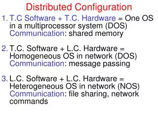
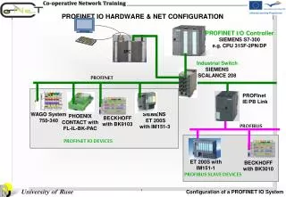
PROFINET IO HARDWARE & NET CONFIGURATION
PROFINET I/O Controller SIEMENS S7-300 e.g. CPU 315F-2PN/DP. IPC. Industrial Switch SIEMENS SCALANCE 208. PROFINET. PROFInet IE/PB Link. WAGO System 750-340. SIEMENS ET 200S with IM151-3. PHOENIX CONTACT with FL-IL-BK-PAC. BECKHOFF with BK9103. PROFIBUS. PROFINET IO DEVICES.

PROFINET IO HARDWARE & NET CONFIGURATION
E N D
Presentation Transcript
PROFINET I/O Controller SIEMENS S7-300 e.g. CPU 315F-2PN/DP IPC Industrial Switch SIEMENS SCALANCE 208 PROFINET PROFInet IE/PB Link WAGO System 750-340 SIEMENS ET 200S with IM151-3 PHOENIX CONTACT with FL-IL-BK-PAC BECKHOFF with BK9103 PROFIBUS PROFINET IO DEVICES ET 200S with IM151-1 BECKHOFF with BK3010 PROFIBUS SLAVE DEVICES PROFINET IO HARDWARE & NET CONFIGURATION
PROFINET IO Communication Model PROFINET IO SUPERVISORS Network Management Visualization and Parameterization Engineering Web Application Commissioning, Diagnostics Diagnosis, Upload/Download TCP/IP on Ethernet PROFINET I/O Controller Application program withaccess to process signalsvia process image Parameterization, Diagnosis Ethernet Configuration, Production data, Alarms Cyclic data Exchande IRT PROXY PROFIBUS PROFINET IO DEVICES Read and write IO data PROFIBUS SLAVE DEVICES
SUBSLOT 1 = Channel 1 SUBSLOT 1 = Channel 1 SUBSLOT 1 = Channel 1 SUBSLOT 1 = Channel 1 PROFINET IO Device Model SLOT 0 SLOT 2 SLOT 1 • IO-Data is always assigned to a sub slot. Bus-Interface (DAP) • Each sub slot can contain I/O data or alarms. The IO device itself is addressed via Slot0, which acts as the "station proxy". I/O Address N I/O Address N+1 I/O Address N+2 I/O Address N+3 PROFINET businterface (DAP) and PROFIBUS IO modules = PROFINET IO device
SIMATIC HW-Config Configuration Tool From GSD import to exchange of data • Every Ethernet device has the same priority in the network • Decentralised field devices will be assigned to a controller during network configuration • The device description of the field devices is defined in a GSD-file 1 PROFINET IO CONTROLER 2 Ethernet 3 PROFINET IO DEVICE 1 GSD import net configuration in the Engineering Tool The configuration is carried out in the engineering system (for example STEP 7). The configuration and the user program are then transferred to the IO controller. Once you have assigned device names to the IO devices, the data is exchanged between the IO controller and assigned to IO devices automatically. 2 3
Addressing of a PROFINET IO DEVICE The complete address of a PROFINET IO DEVICE therefore includes: • MAC address, which is pre-defined in the device and can usually not bemodified. • Device names which can be freely selected, but which for convenience should reflect therelevant plant part. • IP address, which can also be freely selected, but which follows a firmscheme and which should be selected, similar to the device name, accordingto the assigned plant. If the same address is assigned twice, this may causemalfunctions of PROFINET. Although diagnosis functions areusually still available, data communication is no longerpossible. This error is usually indicated by online engineeringuser interfaces. Some system approaches allow exchanging the MACaddresses in PROFINET IO devices. The same approachapplies to IP addresses. You should ensureuniqueness of the addressing.
Structure of IP addresses Private IPv4 address ranges The green figure of the address is determined by thenumber of available networks while the red figure is determined by the number ofnetwork nodes Example of an IP address = Internet Protocol Length = 4 bytes Format = decimal In the example, 256 stations with the following IP addresses can be connected Class C network Host component Decimal format 192 157 018 032 192.157.018.0 - 192.157.018.255 Binary format 11000000 1001101 00010010 00100000 The zeros in the subnet mask determine the host component Subnet mask 11111111 1111111 11111111 00000000
MAC address (Media Access Control) Ethernet / MAC address =Media Access Control Length = 6 bytes Representation = hexadecimal Example:00-0E-8C-XX-XX-XX Siemens Serial No
Address Assignment with DCP (Discovery and Configuration Protocol) Device name is assigned to a MAC-Address 1 • Offline Configuration • Each Device receives a device name (e.g. Siemens coupler) • Configuration tool automatically assigns the IP-Address Online Write device name into the device PROFINET IO CONTROLER 2 3 Ethernet MAC Addr 2 Start up IO Controller assigns IP-Address to the device MAC Addr 1
Address assignment Specific PROFINET devices, such as the distributed I/O ET200 ecoPN, havenomodule slot on account of their construction type. These PROFINET devices and someothers support the PROFINET functionality "Device replacementwithout removable media /PD" C-PLUG contain the Device name transfer the device data from thePC/PC directly to the MMC 192.168.100.3 MMC contains the Device name and IP Address • CPU: • The device name and the IP address are transferred during the startup of the CPU in thesystem data block (SDB). • The IP address is assigned usingthedevice names in the table. MMC contain the Device name
Basic steps from planning to operating a plant Setting up and operating an automation system with STEP 7 PC involves the following basic steps: • Planning the system • Configuring the system with STEP 7 • Commissioning and testing the plant • Operating the plant. • Performing maintenance and modifications.
Configuring the system with STEP 7 - SCENARIO • From Creating the Project to Starting Hardware configuration Tool • Hardware Catalog and Insert new GSD File • Configuring PROFINET IO Controller • Integrating the Industrial switch (SCALANCE X208) into the PROFINET IOsystem • Integrating the ET200S into the PROFINET IOsystem • Integrating Non SIEMENS PROFINET IO Devices • Network transition: IE/PB - Link PN IO • Hardware configuration • Rack, Slots, Electronic Modules • Addressing S7-300™ Modules • Configuring the PROFINET interface • Assign parameter to PN Interface • Insert GSD files in Hardware catalog • Insert the IO Devices from: PROFINET IO -> Additional Field Devices and Insert the necessary components in the configuration table • components in the configuration table • Adjustthe IP address and the devicename. • Set IO Cycle parameters • Adjust Parameter tab • Assigning Device name and IP Address • Configuring Alarms • Configuring Media redundancy tab • Prioritizing startup • Configuring the topology • Insert Device from Hardware catalog • Properties of PROFIBUS DP Interface • Properties of PROFINET IO Interface • Integration of DP slaves • Hardware configuration Rack, Slots, Electronic Modules • Assigning a device name to the IO device ET 200S PN • Configuring the PROFINET interface • Synchronization tab • IO Cycle Tab • Prioritized startup • Setting up the communication ports
From Creating the Project to Starting Hardware Configuration Tool generate a new project 1 Insert Station 2 project name storage location starting the hardware configuration tool 3
Hardware Catalog and Insert new GSD File Start “Install New GSD File” Function 2 The title bar Hardware Catalog button 1 The new devices are in Hardware configuration Window 3 Hardware Catalog Window
Configuring the PROFINET IO Controller 1. Rack, Slots, Electronic Modules Hardware catalog plain list Slot 1 Power Supply Slot 2 CPU Module with PN Interface Slot 3 Reserved Slot 4 -11 Electronic Modules detailed view
Configuring the PROFINET IO Controller 2. Addressing S7-300™ Modules Slot No. 1 2 4 5 6 7 8 9 10 11 Modules PS CPU SM SM SM SM SM SM SM SM Address 0.0 Address 0.7 Address 1.0 Address 1.7
Configuring the PROFINET IO Controller 3. Configuration of the PROFINET interface 1 2 3 • Select the module, the PROFINET interface • Assign a name to IO controller • Enter desired IP address and Subnet mask • Confirm window with OK 4
Configuring the PROFINET IO Controller 4. Assign parameter to PN Interface
Integrating the SCALANCE X208 into the PROFINET IOsystem 1. Insert Device from Hardware catalog
Integrating the SCALANCE X208 into the PROFINET IOsystem 2. Assign Device name and IP Address If you want to operate IE Switches X200 that were previously configured over PROFINET without PROFINET functionality, the devices must be reset to the factory defaults. You can do this with the "Reset to Factory Defaults" function in the Web Based Management or by pressing the button when you turn on the power supply.
Integrating the SCALANCE X208 into the PROFINET IOsystem 3. Configuring Alarms Select the switch 1 Adjust Alarms in Parameters tab 3 Double –click and open "Object Properties" tab 2 System default
Integrating the SCALANCE X208 into the PROFINET IOsystem 4. Configuring Media redundancy tab Select Media Redundancy tab 2 1 Open dialog box mrpdomain-1 default-mrpdomain 3 4 5 6 "Manager" if you want the device to operate as redundancy manager. "Client" if the device is part of a redundant network. "Not node in the ring" if no medium redundancy is configured
Integrating the SCALANCE X208 into the PROFINET IOsystem 4. Configuring Media redundancy tab - Continued Select Media Redundancy tab 2 1 Open dialog box mrpdomain-1 default-mrpdomain 3 4 5 6 "Manager" if you want the device to operate as redundancy manager. "Client" if the device is part of a redundant network. "Not node in the ring" if no medium redundancy is configured • To ensure problem-free operation when using a third-party device as the redundancy manager in the ring, make sure that you assign the fixed role of "Redundancy client" to all other devices in the ring, before you close the ring. Otherwise, there may be circulating data frames that will cause a failure in the network. • If you reset to the factory settings, the ring port settings are also reset. With the appropriate attachment, a ring node that was previously correctly configured can cause circulating frames and loss of the data traffic. • If you reset to the factory settings, the MRP role of the device is also reset. If you are operating a third-party device as the redundancy manager in the ring, this may cause loss of the data traffic.
Integrating the SCALANCE X208 into the PROFINET IOsystem 5. Prioritized startup 1 Open dialog box If you configure MRP in a ring, you cannot use the "prioritized startup" function in PROFINETapplications on the devices involved. If you want to use the "prioritized startup" function, then disable MRP in the configuration. In the STEP 7 configuration, properties dialog of the PROFINET interface > "Mediaredundancy" tab > "MRP configuration" box, set the role to "Not node in the ring" in the “mrpdomain1“domain. The start-up times for Prioritized Start-Up are reduced to 2 seconds.
Integrating the SCALANCE X208 into the PROFINET IOsystem 5. Configuring the topology 2 Select Topology tab 1 Open dialog box Only for fiber-optic cable • You can interconnect devices under "Partner port" if: • The port is connected to the Ethernet subnet • Other PROFINET devices are connected to a port on the subnet • The devices support topology configuration This area is only available if the device supports IRT and no alternating partner is configured.
Integrating the SCALANCE X208 into the PROFINET IOsystem 5. Configuring the topology - Continued 2 3 1 Open dialog box Ensure that the setting for the local port and the partner port are identical.
Integrating the ET200S into the PROFINET IOsystem 1. Insert Device from Hardware catalog. Rack, Slots, Electronic Modules Select IO Device 1 Power Module Output addresses, band model Input addresses, band model Select IO Modules 2
Integrating the ET200S into the PROFINET IOsystem 2. Assigning a device name to the IO device ET 200S PN (Offline). Double Click Device names IP addresses and MAC addresses must be assigned, so that an IO device can be uniquely assigned to an IO controller.
Integrating the ET200S into the PROFINET IOsystem 3. Assigning properties to PROFINET Interface. For the effects on the reaction time with a setting "> 1 m", refer to the relevant manual.
Integrating the ET200S into the PROFINET IOsystem 3.1. Synchronization tab This tab displays the synchronization properties of the IO controller. See slide 16 Double Click 1 2 3
Integrating the ET200S into the PROFINET IOsystem 3.2. IO Cycle Tab Double Click 1 2 Send clock set in the sync domain. See slide 16 3 The update time can only be changed when there are no synchronized PROFINET IO devices in the IO system Maximum watchdog time: 1.92 seconds.
Integrating the ET200S into the PROFINET IOsystem 3.3. Prioritized startup Double Click 1 2 3 The check box can only be selected if the IO controller you are using can prioritize selected IO devices during startup. 4 Within a PROFINET IO system, you can only prioritize a certain maximum number of IO devices that depends on the IO controller you are using.
Integrating the ET200S into the PROFINET IOsystem 3.4. Setting up the communication ports This section shows the name of the local port. The window shows the ports on all devices that support the function topology and are not yet connected to the network
Integrating the ET200S into the PROFINET IOsystem 3.5. Setting up the communication ports/ Disable autonegotation Autonegotiation - operating parameters of the connected network are detected and the data transmission speed and transmission mode are optimally set.
Integrating Non SIEMENS PROFINET IO Devices • Insert GSD files in Hardware catalog (slide 12) • Insert the IO Devices form PROFINET IO -> Additional Field Devices (slide 25) • Insert the necessary components in the configuration table (slide 25) • Adjustthe IP address and the devicename. (slide 26) • Set IO Cycle parameters (see slide 29) • Adjust Parameter tab For the following input modules For first Input module Example refers to WAGO System 750/753
Integrating Non SIEMENS PROFINET IO Devices • Insert GSD files in Hardware catalog (slide 12) • Insert the IO Devices form PROFINET IO -> Additional Field Devices See (slide 25) • Insert the necessary components in the configuration table (slide 25) • Adjusting the IP address and the devicename. (slide 26) • Set IO Cycle parameters (slide 29) • Adjust Parameter tab Example refers to WAGO System 750/753
Integrating Non SIEMENS PROFINET IO Devices • Insert GSD files in Hardware catalog (slide 12) • Insert the IO Devices form PROFINET IO -> Additional Field Devices See (slide 25) • Insert the necessary components in the configuration table (slide 25) • Adjustthe IP address and the devicename. (slide 26) • Set IO Cycle parameters (slide 29) • Adjust Parameter tab A port that is physically present in a module but is not available as a port submodule in the STEP 7 environment, is referred to as a default port. Such ports are only displayed in the Topology Editor (i.e. they are not in the configuration table) and can only be interconnected here. Example refers to WAGO System 750/753
Network transition: IE/PB - Link PN IO The C-PLUG may only be inserted or removed when the power is off.A screwdriver can be used as an aid. In the case of changeover from use as a PROFINET IO device or as a network transition, a reset to factory settings is always necessary.
Integration of IE/PB Link PN IO 1. Insert Device from Hardware catalog
Integration of IE/PB Link PN IO 2. Properties of PROFIBUS DP 1 2 3
Integration of IE/PB Link PN IO 2. Properties of PROFONET IO Interface the highest unassigned number
Integration of IE/PB Link PN IO 3. Integration of DP slaves. Rack, Slots, Electronic Modules
Connect all participants in the network, according to a topology and Switch On the power supply • Commissioning of the automated system with the PROFINET IO network is done in the following sequence • Switching the PG interface on the network card from the "Ethernet" type and Assigning an IP address for PG/PC • Node initialization for the IO controller, i.e. assign the IP address to theIO controller • Transfer device names for each individual IO device one-by-one • Transfer hardware configuration of the overall system to the IO controller • Transfer S7 program to the IO controller PROFINET IO COMMISSIONING
Switching the PG interface on the network card from the "Ethernet" type 3 1 2 4 5
Assigning an IP address for PG/PC Select the "TCP/IP" network protocol Fixed IP address for PG/PC interface 1 3 4 2 Access path through TCP/IP In the following examples, the IP address • 192.168.100.99 should be used for the PG/PC and • 192.168.100.1 should be used for the CPU 315F-2 PN/DP (subnet mask 255.255.255.0). Check the IP address ranges suggested bySTEP 7 with reference to your actual system.
Assigning an IP address for PG/PC - Test for real connections Accessible Nodes Button These devices are used for the first time or have an erased MMC. Theyhaveonly a MAC address and no name. In many devices the command Resest to factory setting erases only the IP address and parameters of the PN IO interfaces, without deleting the name
Assign IP address to theIO controller At this stage, all participants in the network have invalid IP addresses Select the IO Controller CPU
Assign IP address to theIO controller Result: IO controller is assigned a name and IP address Insert IP Address and Subnet mask Confirm address Insert IP Controller name and Confirm with button
Assign Device Name 2 3 1 Check compliance with the names • Select the desired device. • Select the corresponding name. • Confirm with the button "Assign name"
Switch the IO controller from STOP to RUN There are two types of LED displays on SIMATIC S7 PROFINET IO devices: • General status and error displays • Status displays for the communication interfaces PHOENIX CONTACT FL-IL-BK-PAC Please see the manufacturer documentation for the detailedfunctions of the PROFINET node displays. UL SF BF UM COL US XMT RCV LNC SFSystem error present BFNo link status available COLCollision of data telegrams XMTData telegrams are being sent RCVData telegrams are being received LNKPhysical network connection ready to operate SFSystem error present 5V DC The 5V supply for CPU and S7-300 bus OK FRCE Force job Active BF1 Bus fault at the PROFINET interface BF2 Bus fault at the ETHERNET interface LINK A connection to PROFINET has not been established RX/TX The port sends or receives data