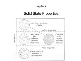
Solid State Detectors and Instrumentation
Solid State Detectors and Instrumentation. Davin Larson 2008-04-23. Solid State Detectors and Instruments - Outline. Outline: Energy loss in Matter Energetic Particle Detectors Instrument Design. Solid State Detectors and Instruments - Outline. Outline: Energy loss in Matter Photons


Solid State Detectors and Instrumentation
E N D
Presentation Transcript
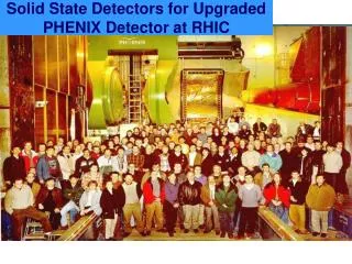
Solid State Detectors and Instrumentation Davin Larson 2008-04-23 UCLA
Solid State Detectors and Instruments - Outline • Outline: • Energy loss in Matter • Energetic Particle Detectors • Instrument Design UCLA
Solid State Detectors and Instruments - Outline • Outline: • Energy loss in Matter • Photons • Charged Particles • Ions • Electrons • Energetic Particle Detectors • Instrument Design UCLA
Energy loss in Matter • The manner in which energetic particles interact with matter depends upon their mass and energy. • Photons - have “infinite range”- Their interaction is “all-or-nothing” They do not slow down but instead “disappear”, typically through 1 of 3 interactions: • Photoelectric effect (Low energy: E<~50 keV • Compton Scattering (50 keV ~< E < 1 MeV) • Pair production ( E >2 x 511 keV). • Particles with non-zero mass (Electrons and Ions) will slow down as they pass through matter. UCLA
Energy Loss in Matter – Particles with mass • Charged particles primarily interact with the electrons in a material. Typically the energetic particle suffers numerous, distant collisions with a Fermi sea of electrons losing a small amount of energy with each interaction (much like a plasma!). • The interaction is typically strongest when the velocity of the energetic particle is approximately the same as the Fermi speed. • Energetic neutral atoms are quickly ionized soon after entering the solid. • Neutrons are a different matter altogether UCLA
Energy Loss in Matter • The stopping power for heavy particles is given by the Bethe-Bloch formula (1932): Where: Rate of energy loss is ~ inversely proportional to energy, and proportional to z, (the effective charge) UCLA
The range is given by: This formula is only useful for ions for reasons we will soon see. UCLA
Some Useful Software tools for determining /simulating the passage of particles through Matter • NIST – stopping power and range • Estar - electrons • Pstar - protons • Astar - alphas • CASINO – Electron propagation • SRIM – Ion Propagation • GEANT –Does everything! UCLA
Energy Loss in Matter -Electrons Alphas in: Electrons in UCLA
Energy Loss in Matter- Protons Protons in UCLA
Energy Loss in Matter - Alphas Alphas in: Energy lost to ionization (collectable) Energy lost to phonons (not collectable) UCLA
Energy Loss in Matter – Differences between electrons and ions • Electrons and Ions behave differently due to the different mass ratio: • The primary interaction of all energetic particles is with the sea of electrons. • Ions interact with a series of distant collisions. Each interaction results in a small energy loss and very little angular scattering. – They travel in nearly straight lines as they slow down. The dispersion is small. (Imagine a fast bowling ball thrown into a sea of slow moving ping pong balls.) • Electrons can lose a large fraction of their energy and undergo large angle scattering with each interaction (Imagine a high speed ping pong ball thrown into the same sea) UCLA
When an electron hits an atom it can undergo a very large angle deflection, often scattering it back out of the material. • Bremstrahlung (breaking) radiation is produced when electrons undergo extreme accelerations. X-rays are easily generated when energetic electrons strike high Z materials. (a good reason to avoid high Z materials on exposed surfaces) UCLA
Solid State Detector – Simulation tools • CASINO - " monte CArlo SImulation of electroN trajectory in sOlids ". • A very useful simple tool that simulates electron propagation within solids • Developed for electron microscopy • http://www.gel.usherbrooke.ca/casino/index.html This program is a Monte Carlo simulation of electron trajectory in solid specially designed for low beam interaction in a bulk and thin foil. This complex single scattering Monte Carlo program is specifically designed for low energy beam interaction and can be used to generate many of the recorded signals (X-rays and backscattered electrons) in a scanning electron microscope. This program can also be efficiently used for all of the accelerated voltage found on a field emission scanning electron microscope(0.1 to 30 KeV) UCLA
CASINO Simulation • Simulation of 30 keV electrons in Silicon Electron Trajectories (16 % backscattered in red) Distribution of Maximum Z value. Mean: 45 microns UCLA
Ion simulation software • SRIM/TRIM “Stopping and Range in Matter” • Only for ions • Download from: http://www.srim.org/ • Simple to use. 30 keV proton in Si Range: 3 microns UCLA
TRIM Simulation - 30 keV • Simulation results for 30 keV ions in Silicon detector Ionization energy not collected in 400 Angstrom Dead layer UCLA
CASINO Simulation 350 keV protons 400 keV protons Lexan Si Al UCLA
Energetic particle simulation tools • GEANT4 – GEometry ANd Tracking • The ultimate simulation tool • Developed at CERN for high energy particle accelerators and detectors • Allows complex 3D geometries • Simulates all particles (electrons/ion/photons) and recursively tracks all daughter products. • Fairly difficult to use. • May not be accurate at low energy (<10 keV) ? • Now available on WINDOWS/XP! • More info at: http://geant4.web.cern.ch/geant4/ UCLA
Energy loss in Matter • Energetic Particle Detectors: • Solid State Detectors • Silicon Solid State Detectors • PIPS • Surface Barrier • Lithium Drifted Silicon • High Purity Germanium • Light producing detectors • Scintillators • Organic • Inorganic • Cherenkov Radiators • New Technologies • Avalanche Photodiodes • CCD Readout • Delta-doped • Instrument Design, Test and Calibration Instruments UCLA
Energetic Particle Detectors • Solid State Detectors (SSDs) not only detect individual particles, they can be used to measure particle energy with good energy resolution. • Typically only good for E>20 keV • Recent improvements push the limit to ~2 keV UCLA
Silicon Diode Detectors • Two varieties of Silicon Diode Detectors • Implanted Ion (i.e. Canberra PIPS) • Produced by implanting p-type material into an n-type silicon substrate • Easy to produce pixelated surfaces • Very rugged • Surface Barrier • Chemical process to create diode surface • Easily damaged, sensitive to solvents • Not too common anymore • Typically both varieties are run fully depleted (electric field extending throughout bulk of material) • Maximum thickness is ~1000 microns – defines max energy particle that can be stopped within the detector • Particles can be incident on either side of detector UCLA
Other Detectors Continued… • Lithium Drifted Silicon • Requires (?) LN2 storage for stability • Can be made in thicknesses up to 1 cm to stop very energetic ions (~100 meV) • Reduced energy resolution for ion studies • HP (High Purity) Germanium • Expensive! • Large Z high stopping power • Very large form factor are possible • Generally used for x-rays, gamma-rays • CdZnTd (Cad Zinc Telluride) • High Z • Cheaper than Ge UCLA
Solid State Detectors – Principle of operation • With the application of a (large enough) reverse bias voltage an electric field is established throughout the silicon. • An energetic charged particle will leave an ionization trail in its wake. • The electron hole pairs will separate and drift to opposite sides. • The total charge is proportional to the electronic energy deposited. (3.61 eV per pair for Silicon). • The signal contains only a few thousand electrons thus requiring sensitive electronics. • The trick is to collect and measure this small signal. Energetic Particle E Ionization trail e- h+ E UCLA
Other detector types • Scintillators • Emit light when charged particle traverses the material. • Light output is approximately linear with deposited energy • Light is typically collected with a photomultiplier • Easily shaped to accommodate instrument requirements • Relatively poor energy resolution • Often used as active shielding (veto device) or as final stop for very energetic particles (cosmic rays) • Two Classes: • Inorganic (Ionic crystals, ie. NaI is very common) • High stopping power (high Z) • Organic (plastics) • Generally have low stopping power • Very fast (good for coincidence events) • Cherenkov Detectors • Utilizes Cherenkov radiation emitted when a particle travels faster than speed of light in that medium (extremely relativistic particles only) UCLA
Instrument Design • Energy loss in Matter • Energetic Particle Detectors: • Instrument Design • Issues to be aware of: • Choice of shaping time/ • Pulse Height Defect • Dead Layers • Radiation Damage • Light Sensitivity • Paralyzibility of charge sensitive amplifiers • Pulse Pileup • Electronic Noise Limitation • Cooling / Temperature sensitivity • Micro-acoustic sensitivity • Magnetic cleanliness UCLA
Solid State Telescope examples –WIND EPACT Cross section of the EPACT isotope telescope on Wind. The first two detectors are two-dimensional position sensitive strip detectors (PSD1, PSD2). They are required so that path-length corrections may be made for the angle of incidence and for non-uniformities in detector thickness. Tungsten rings are used to mask off circular areas for each PSD. There are 6 solid-state detectors increasing in thickness with depth in the stack in order to minimize Landau fluctuations. From von Rosenvinge et al. [1995]. UCLA
Examples of High energy particle instruments • Proposed Instrument that combines SSDs, active shielding, and scintillators. Used to detect particles >400 MeV UCLA
Sensor Unit Schematic Foil Detector Al/Polyamide/Al Foil Thick Detector Open Detector Foil Collimator Open Collimator Attenuator Attenuator Sm-Co Magnet From PDR
Sensor Cross Section Foil Collimator Attenuator Foil Detector Stack Magnet Attenuator Open Collimator From PDR
Overview • Solid State Telescope (SST) • Requirements and Specifications • Block Diagram • Mechanical Design • Detectors • Collimation • Magnets • Attenuator (aka shutter, door) • Detector placement / FOV issues • Mass estimates • Electrical Design • DFE – (Detector Front End) • DAP – (Data acquisition and Processing) • Power Estimates • Testing and Calibration • Schedule • Issues UCLA
Science Requirements • SST-1: The SST shall perform measurements of the tailward-moving current disruption boundary speed using the finite gyroradius technique (4.1.1.2, 4.1.1.5). • SST-2: The SST shall measure the time-of-arrival of superthermal ions and electrons of different energies emanating from the reconnection region to determine the Rx onset time (4.1.1.3, 4.1.1.5). • SST-3: The SST shall compute the partial energy moments due to the superthermal ions and electrons in the magnetotail plasma sheet (4.1.1.3, 4.1.1.6, 4.1.1.7, 4.1.1.9, 4.1.1.10). • SST-4: The SST shall obtain measurements of ion and electron distribution functions with one spin time resolution (<10sec required) (4.1.1.2, 4.1.1.3). • SST-5: The SST shall measure energetic electron fluxes as close to Earth as 6RE geocentric, at all local times. (Radiation belt science- tertiary objective – achieved by nominal design). • SST-6: The SST shall measure energetic ions in the solar wind, at the magnetopause and in the magnetosheath (Dayside science – secondary objective – achieved by nominal design). Example Requirements UCLA
Performance Requirements • SST-7: The SST shall measure energetic particles over an energy range of 30-300keV for ions and 30-100keV for electrons found in the magnetotail plasma sheet (SST-1, SST-2). • SST-8: The SST energy sampling resolution, dE/E, shall be better than 30% for ions and electrons (SST-1, SST-2). • SST-9: The SST shall be capable of measuring differential energy flux in the range from: 10^2 to 5x10^6 for ions; 10^3-10^7 for electrons (keV/cm2-s –st- keV) whilst providing adequate counts within a 10 second interval. (exact values TBD) (SST-1, SST-2) • SST-10: The SST shall measure over 90o in elevation with a minimum resolution of 45o (SST-1, SST-2, SST-3, SST-4). • SST-11: The SST shall have an azimuthal resolution of 45o (SST-1, SST-2, SST-3, SST-4). • SST-12: The SST shall supply the high energy partial moments at one spin time resolution (SST-3) • SST-13: SST calibration shall ensure <20% relative flux uncertainty over the ranges defined above (SST-1, SST-2). Example Requirements UCLA
Overview • Solid State Telescopes: • Measure Energetic Electrons and Ions • Energy Range: • H+: 25 keV to 6 MeV (possible ~2 MeV) • Electrons 25 keV to ~800 keV • Angular Coverage: • Theta • 4 look directions (+55, +25, -25, -55) • Resolution: ~ 30 deg FWHM • Phi • 32 sectors • Resolution: ~20 deg FWHM • Geometric Factor: ~0.1 cm2-ster (~1/3 of WIND) • Pinhole Attenuator: Cuts geometric factor by 64 UCLA
Block Diagram IDPU Sensor Unit 1 (2 DFEs A&B) SST DAP Board ETC Board DCB Sensor Unit 2 (2 DFEs A&B) UCLA
Sensor Units • Each sensor unit is a: • Dual-double ended solid state telescope • Each double ended telescope (1/2 sensor) has: • Triplet stack of silicon solid state detectors • Foil (on one side) • Filters out ions <~350 keV • Leaves electron flux nearly unchanged • Magnet / Open side • Filters out electrons <400 keV • Leaves ion flux nearly unchanged • Mechanical Pinhole attenuator • Reduces count rate during periods of high flux • Reduces radiation damage (caused by low energy ions) during periods of high flux • Collimators • Preamplifier / shaping electronics UCLA
Sensor Unit Schematic Foil Detector Al/Polyamide/Al Foil Thick Detector Open Detector Foil Collimator Open Collimator Attenuator Attenuator Sm-Co Magnet UCLA
Sensor Cross Section Foil Collimator Attenuator Foil Detector Stack Magnet Attenuator Open Collimator UCLA
Design Details Thomas Moreau UCLA
Sensor Considerations • Detector system • Measure electrons and protons > 20 keV • Geometrical analysis • Collimator aperture • Solid state detector size • Thin foil • Stop protons < 350 keV • Magnet system • Deflect electrons < 400 keV • Not to disturb particle trajectories out of the magnet gap • Low stray magnetic field at the position of the magnetometers • Attenuator System • Reduce count rate during high flux • Reduce radiation damage (especially to open side) UCLA
F T O Detector System • Detectors stacked in “Triplet” sequence: • Foil (F) | Thick (T) | Open (O) • Area used 1.32 0.7 cm2 • Front detectors F and O are 300 m thick while T is 600 m (with two detectors back to back) • Detectors associated with a system of coincidence/anticoincidence logic UCLA
Collimator System • 3D numerical model (GEANT3) of the collimator with detectors/foil • Collimator baffle offers 42 23 rectangular full field-of-view • Be-Co knife-edges intercept out-of-beam low-energy particles and reduce scattered light • Aluminum housing shielding (0.5 mm) stops normally incident protons < 8 MeV and electrons < 400 keV • Al/Polyimide/Al (LUXÉL) three layer foil (~1500Å/4m/1500Å) absorbs protons < 350 keV while permitting electrons ~20 keV to penetrate • Geometric factor ~ 0.1 cm2sr UCLA
Telescope Response • Monte-Carlo simulation • 3D ray tracings are performed: a clean electron-proton separation is obtained • Particles’ angular distributions are determined ( 27 14 FWHM) • Efficiency plots of the electron-proton detectors are determined for different energies UCLA