Download
1 / 32
320 likes | 488 Views
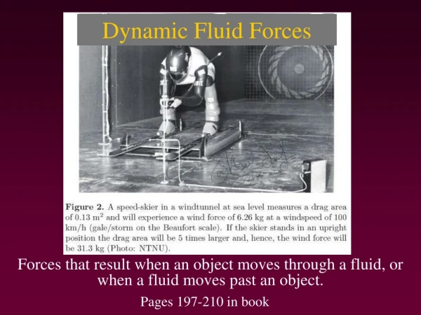
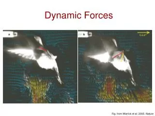
Dynamic Forces. Fig. from Warrick et al. 2005. Nature. F. Solids vs. Fluids. S. . Solids resist shear deformation: they care how far they are deformed. Fluids care about how rapidly they are deformed: rate of shear. F/S = (/t). F/S = G . Dynamic viscosity. Shear modulus.

E N D
Dynamic Forces Fig. from Warrick et al. 2005. Nature
F Solids vs. Fluids S Solids resist shear deformation: they care how far they are deformed Fluids care about how rapidly they are deformed: rate of shear F/S = (/t) F/S = G Dynamic viscosity Shear modulus Rate of shear Shear strain
No-slip condition & Boundary layer U F S (F/S) = (U/z) z Lingulodinium polyedrum
Viscosity U F S z F/S = (/t) Viscosity is a measure of the resistance to rate of shear
Physical coupling of temperature and viscosity Viscosity of water has a sever dependence on temperature (Viscosity doubles from 30 to 5ºC)
Temperature effects on viscosity * More viscous blood should flow more slowly * Slower mass flow can minimize heat loss Q’ = CJΔT
Temperature effects on viscosity Leopard Seal Crabeater Seal Weddell Seal Blood viscosity triples as temperature decreases (38 - 3ºC)
Principle of Continuity A1V1 = A2V2
Principle of Continuity: example Total Area Flow speed Aorta 200 mm2 200 mm s-1 Capillaries 1 mm s-1 5.7 x 104 mm2
Continuity in flow fields Narrow streamlines A1V1 = A2V2 The principle of continuity must apply between a pair of streamlines
Pressure exerted in all directions by a fluid at rest Static Pressure Dynamic Pressure Δp U Δp = ½ρU2 • Measurable pressure when fluid is brought to a halt
Bernoulli’s Principle Pressure Drop = ρgh P1+ ½ ρV1 = P2 +½ρV2 Fluid has a local static and dynamic pressure: the sum of these is constant
Bowhead Whale: Continuous filter feeder (Werth 2004, J. Exp. Biol. ) Anterior Opening Posterior Opening
A1 A2 A2 A1 Venturi manometer Showing pressure drop A1 A2 Bernoulli: ΔP = ρu2/(1-A12/A22) Pressure drop (Werth 2004, J. Exp. Biol. )
Difference in dynamic pressure creates drag Momentum = mU Dynamic pressure = ½ ρU2 1.0 Cp = Measured pressure 0.5 ΔP → Drag Cp Dynamic pressure 0 -0.5 • Flow is redirected around the body, flow is robbed of its momentum • Momentum lost in wake (eventually in the form of heat)
Difference in dynamic pressure can also create lift No lift, little drag Lift, Little Drag Stall: Lift & Drag FL = ½ CLSρU2 Fluid separates from surface: vortices & eddies are generated
Vortex Street st = StU/D Frequency of Vortex Shedding Diameter Strouhal Number(non-dimensional)
Why drag is important 1. Drag = mass x acceleration Thrust = Drag 2. Work against drag = drag x distance Δx 3. Energy expenditure or Power = drag x velocity Δx Δt
Drag: resists motion through fluid D = Fh + Fs + Fw + Fi Total Drag Skin Friction Wave Drag Induced Drag Hydrodynamic or Pressure Drag Thrust Total Drag
Drag: resists motion through fluid D = Fh + Fs + Fw + Fi Total Drag Skin Friction Wave Drag Induced Drag Hydrodynamic or Pressure Drag U S = flow-wise area Fh = ½ CDSρU2 Due to separation & ΔP, E is invested in moving fluid around object, but isn’t being returned back to the fluid
Drag: resists motion through fluid D = Fh + Fs + Fw + Fi Total Drag Skin Friction Wave Drag Induced Drag Hydrodynamic or Pressure Drag U A = “wetted” surface area Fs = ½ CDSρU2 A direct consequence of the interlamellar stickiness of fluid
Skin friction vs. Pressure drag Flow remains attached, drag dominated by skin friction Early separation,high pressure drag relative to skin friction
Drag: resists motion through fluid D = Fh + Fs + Fw + Fi Total Drag Skin Friction Wave Drag Induced Drag Hydrodynamic or Pressure Drag Wave drag occurs near the sea surface
Drag: resists motion through fluid D = Fh + Fs + Fw + Fi Total Drag Skin Friction Wave Drag Induced Drag Hydrodynamic or Pressure Drag Drag Lift Drag generated by the oscillation of appendages
What is the drag coefficient, CD? U Fh = CdS½ρU2 Dynamic pressure Projected Area Drag
D = CdS½ρU2 Drag depends on shape: Dynamic pressure drag Flow-wise projected area 0.2 0.4 0.6 0.8 1.0 1.2 1.4 Drag coefficient (Cd)
CD can get even bigger during unsteady motion CD → 2.0 (Potvin, SLU)
ρLU Reynolds number (Re) = ν ρ = density U = velocity L = length v = viscosity Drag also depends on scale D = CdS½ρU2 Low Re Intermediate Re High Re Cd Re
Life at low Reynolds numbers D = CdS½ρU2 • Viscous • Difficult to produce vortices • Efficiency of locomotion decreases • Many organisms resort to dragging themselves through the medium • High Cd
Drag reduction: Convergence on streamlined form What happens when animals deviate from this ideal form?