Download
1 / 37
370 likes | 478 Views
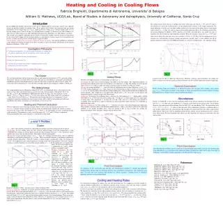
INTRACLUSTER MAGNETIC FIELDS AND THE REHEATING OF COOLING FLOWS. D. S. De Young National Optical Astronomy Observatory. 3 June 2003. The Riddle of Cooling Flows - Charlottesville. Extended Radio Sources in Clusters. Vast Majority are FR-I’s ~ ½ Show “Normal” FR-I Morphology

E N D
INTRACLUSTER MAGNETIC FIELDS AND THE REHEATING OF COOLING FLOWS D. S. De Young National Optical Astronomy Observatory 3 June 2003 The Riddle of Cooling Flows - Charlottesville
Extended Radio Sources in Clusters • Vast Majority are FR-I’s • ~ ½ Show “Normal” FR-I Morphology • ~ ½ Show “Tailed” Morphology • Slightly more WAT than NAT • Radio Luminosities: 10 - 10 erg/s • Total Energies: ~ 10 ergs 41 44 59
Radio Sources in Clusters • Head-Tail Sources – A Known Interaction?
Radio Sources in Clusters • Still Some Mysteries… O’Donoghue, Owen & Eilek 1990
Radio Source Cavities • Chandra A2052 + 6cm VLA (3C 317) Blanton et al. 2001, Burns 1990
Radio Source Cavities • A2052
Properties of Radio Source Cavities and Shells • Morphology • Limb Brightened, “Relaxed” Structure • NOT Head-Tail or “Normal” FR-I • No Jets, but t ~ 10 yr • Tens of kpc in Diameter • Inferred Properties • In Pressure Equilibrium • Moving Subsonically (no Shocks) • Shell and Surroundings Cool 7 syn
Inferred Physical Model of Radio Sources Cavities • Low Internal Density • High Internal Pressure • Energy Density ~ 10 x Equipartition • Thus… • Buoyant Bubbles
Radio Source Bubbles and Cooling Flows • Total Radio Source Energies Are a Significant Fraction of ICM Energy Budget • Old Idea • Need to Convert Kinetic and Particle Energy into Heat • Via Turbulent Mixing with ICM • Via Advection and Mixing of ICM • Via Shocks in ICM • Is There Enough Time to Do This?
Models of Buoyant Radio Source Bubbles • 3-D Hydrodynamic 10 x 10 x 30 kpc 8 Myr 25 Myr 41 Myr 59 Myr Density Brueggen et al. 2002
Models of Buoyant Radio Source Bubbles Density • 2-D Hydrodynamic X-Y High Resolution Brueggen & Kaiser 2002
Suggested Reheating Mechanisms • Mixing of ICM and Radio Source Material • Lifting of ICM in Wakes of Buoyant Bubbles • Entrainment of ICM Along Surface of Rising Bubbles • Self Consistent Mixing Calculation Not Yet Done
But It’s Suggestive… However…
Relic Radio Sources in Clusters • A2597 VLA 1.4 GHz McNamara et al 2002.
Relic Sources in Clusters • N1275 74 MHz Fabian et al. 2002
Properties of Radio Relics • They Are Intact! • Reside 30-50 kpc From Cluster Center • Diameter 10-20 kpc • Buoyant Risetimes >> Synchrotron Life • Reacceleration • Equilibrium Implies U >> U • PdV Work ~ 10 erg int equip 59
Consequences of Relic Radio Sources • Magnetic Effects Cannot Be Neglected • Ambient Fields of 1-10 uG Exist in ICM • Expansion of Bubble Will Cause Sheath of Enhanced Tangential Field Around Bubble • This Will Suppress R-T and K-H Instability • R-T: Stable for • K-H: Stable for
Linear Stability Analysis • Gives Conditions for Onset of Instability • At r ~ 50 kpc, n = 0.01, B = 3 x 10 G: • R-T: l = 13 kpc, t = 7 x 10 yr • K-H: Stable for U ~ 0.1 c • Thus: No Fragmentation or Mixing for a Significant Fraction of Buoyant Risetime -6 7 O O s
Non-Linear MHD Calculations • Three Dimensional MHD TVD Code • Collaboration with T. Jones • (Jones, Ryu, Kim, Tregillis, etc. 1999 – 2001 • Time Dependent Evolution of Buoyant Radio Relics in a Stratified ICM • R – T Instability • Destruction of Relic and Mixing with ICM • Lifting and Mixing of Different Elements of the ICM
Non-Linear R-T Instability t = 0 Beta = 1.3 M Beta = 1.3 K 130 ~ ICM 1 kpc slices T = 10M K t = 15 Myr
Another Non-Linear Calculation • 2-D MHD • Tangential Field Inserted “By Hand” Breuggen & Kaiser 2001
Creation of Tangential Field Geometry • 2-D MHD TVD – Self Consistent Field T = 100M K Ro = 5 kpc Bo Uniform n =.2n Beta = 1.2 M b o t = 65 My t = 125 My
Buoyant Relics with Optimal ICM Coupling • 2-D MHD TVD – Self Consistent Field T = 100M K; Ro = 5 kpc Beta =1.2 M Beta =50 t = 65 My t = 125 My t = 150 My
Consequences of B Fields • For Cluster ICM Reheating • Onset of Instability and Mixing Delayed • Initial Scale Length Large: l ~ 10 kpc • Mixing Time to Reheat Will Be Long • How Long? • Time Required for Turbulent Cascade to Go From Energy Range to Dissipation Range • l /v ~ 3 x 10 yr o 7 o turb
Turbulence Features Energy Inertial Dissipation Dissipation
Non-Linear 3-D MHD Turbulence 8 Thus the Time to Reheat the ICM is ~ 4 x 10 yr
ICM Lifting and Mixing • Issues • How Much ICM Is Lifted Per Buoyant Source? • What Are The Effects Of Magnetic Fields? • What Is (Lifted ICM Volume/Source Volume)? • How Is Lifted Material Mixed With The Ambient ICM? • How Often Must This Happen? • Are There Experimental Data?
Lifting With Low Field - Maximally Coupled • Beta = 1.2M
Lifting - Magnetic Effects Beta = 1.2M Beta = 1.3K t = 90 Myr
Lifting and Magnetic Fields • Weak Field Limit – Maximal Coupling • Most Lifting Occurs in Wake of Rising Relic • Volume of Lifted Material Limited to Column Smaller than Bubble Cap • Increasing Beta Alters Bubble Geometry but Not the Volume Lifted • Increasing Beta to ICM value Shows Non-local Effects • Repeated Outbursts and/or Additional Mixing Mechanisms Will be Required to Reheat ICM
ICM B Fields and Radio Source Content • Radio Lobes Isolated from ICM for ~10 yr • Pressure Balance Implies U >> U • What Supplies This Pressure? • Presence of X-Ray Cavities Implies: • Hot, Rarefied Gas (B >> B won’t work) • Dynamical Lifetimes >> Radiative Lifetimes Implies: Reacceleration 8 eq int eq
ICM B Fields and Radio Source Content • If Use Electron-Positron Population (either thermal or low energy end of power law): • Need n ~ 0.001 to get Pressure • This Gives Too Much X-Ray Emission • Can’t Effectively Reaccelerate Via Shocks or Turbulence • Internal Sound Speed is ~ c (very “hot”) • No Shocks or Large Scale Inhomogeneities
ICM B Fields and Radio Source Content • Hot and Rarefied Electron-Proton Plasma • Can Provide Internal Pressure at n ~ 10 and T ~ 10 or n ~ 10 and T ~ 10 • This Will Have Low L (at Chandra Energies) and Will Create X-Ray Cavities • Plasma Can Support Turbulent and Shock Reacceleration • This e – p Plasma Cannot Come From ICM but Must be Advected Out With Radio Source -4 10 -6 12
Conclusions • Relic Radio Source Cavities Provide Evidence for Interaction with a Magnetized ICM • Radio Lobe Interaction With a Magnetized ICM Indicates: • Delay of Onset of Destructive Instabilities • Long Times to Reheat the ICM • Volume of Lifted ICM Limited to Wake Region • Possible Presence of an e-p Plasma Rather than Electron-Positron Plasma Inside Radio Source