Download
1 / 29
290 likes | 471 Views
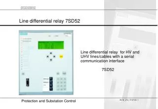
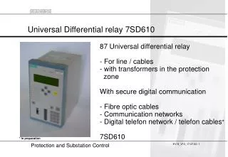
Universal Differential relay 7SD610. 87 Universal differential relay - For line / cables - with transformers in the protection zone With secure digital communication - Fibre optic cables - Communication networks - Digital telefon network / telefon cables * 7SD610. * In preparation.

E N D
Universal Differential relay 7SD610 87 Universal differential relay - For line / cables- with transformers in the protection zone With secure digital communication - Fibre optic cables- Communication networks - Digital telefon network / telefon cables* 7SD610 * In preparation
Protection and communication come togetherThree benefits of the 7SD610 • Differential protection for the universal use with easy to handle settings Two line terminals, Less CT-requirements Handles transformers and compensation coils within the protection zoneTripping time less than one period • Additional functions Backup (parallel running) or emergency O/C - function (3 stages) Breaker failure protection, Overload protection, Switch on to fault feature, 4 fast remote signals, Intertrip function Supervision of the communication link, Bus-wire supervision • Direct and modular connection to fibre optic and digital communication networks
Application - Fibre optic connection Direct connection with fibre optic (FO) cables- Offers high speed tripping (16 ms)- Flexible plug in modules for different fibre typ or distance Distance FO-cable Connector 820 nm, 1,5 km Multimode62,5/125 um STSTSTFC 820 nm, 3 km FO 1300 nm, 10 km Monomode9/125 um 1300 nm, 35 km
E O Communication- system O E Application - Digital communication network Connection via a communication system with multiplexers - Automatic delay time measurement (adaptive correction from 0 ms - 30 ms)- Immediate detection of switch-over conditions of communication routes- Communication addresses, Synchonous electrical interface X.21 (64/128/512 kBit/s) or G703.1 (64 kBit/s) Communicationconverter 820 nm, 1,5 km
O E Application - Leased telefon line Leased telefon line (standby or dial-up) - 2 wire telefon cable (max. 8 km)* Twisted telefon pair max. 8 km (5 miles) E O 820 nm, 1,5 km Communicationconverter 5 kV insulationintegrated * In test
Applications - Line or cable with different CT - ratios 400:5, 10P10, 10VA, kAlf = 59, k = 50 600:1, 5P20, 20 VA, kAlf = 130, k = 33,3 VT optionNot requiredfor diff. function 20 kA ___ IN,CT IK,max k= 87L50/5150 BF49 - Mismatch of the CT ratio of 1:8 allowed, 1A or 5A input settable in the relay- CT datas / errors are set in the relay and automatically considered in the restraint current calculation- CT-requirement: kAlf for the local CT must be greater then k (kmin = 30)
Application -Transformer and line in the protection zone 20 MVA, 110 kV/20 kV, Yd1 10P10, 10 VA, 200:1 10P10, 10 VA, 500:5 1 mile 87T50/5150 BF49 tripcommand - Settings for the transformer datas in each relay with vector group matching, ratio adaption and zero sequence elimination - Differential setpoint is rated to the nominal current of the transformer - Inrush restraint with second harmonic included (time limit for Crossblock) High set element for immetiate trip (16 ms) through heavy fault currents
O O E O Scope of functions / Hardware options Options for the Protection Interface Scope of functions - Fast high set element IDiff>>. Current summation.- Sensitive trip stage with vector summation IDiff> - Autoreclosure 1/3 pole - Communication features - Commissioning aid - Overload protection - Backup-/emergency overcurrent - Breaker failure protection- Switch on to fault protection- 4 remote commands- Intertrip (also from external)- User defined logic- Exact time tagging Relay Hardware 820 nm1,5 / 3 km multimode ST- connector - 3Iph, and IE - 4 U - 7 binary inputs - 5 trip contacts - 1 alarm contact - 1 Protection interface - System interface (option) - Rear DIGSI interface (option) - Time synchronisation interface for GPS internal 1300 nm10 kmmonomode ST- connector internal 1/3 *19´´ O 1300 nm35 kmmonomode FC- connector internal ElectricalX21 G703.1interface 820 nm1,5 kmST-connectors External converter
Service-interface DIGSI local Browser local-PC interface GPS-receiver Serial time sync. input Modular hardware concept with Plug in modules Plug in modules Protection interface 1Port D Remote line end Synchronous N x 64kB/sec Subst. control interface Substation control Communication modules Interfacemodul 2 RS485 or RS232 Available ProtocolsIEC - standard RS485 or FO DIGSI 4; also for modem connectionand Browser Interfacemodul 1 RS485 RS232
Main board of the relay with it´s Communication - Interfaces Main processor board of the relay Sockets for the communicationmodules
Main protection functionFeatures of the differential function • Phase selective differential protection (2 terminals).Tripping time of 16 ms with fast trip stage. • Fundamental vector comparison for the sensitive trip stage. Detects even high resistive faults under full load. • Dynamic increase of sensitive differential setpoint during switch-on of long cables (settable time) • CT saturation detector. Increase of restraint current if CT-saturation is indicated by the measured fault currents. • Phase selective intertrip within 20 ms (normally not required) • Settable delay time for single phase faults (special feature for inductive compensated networks) • Inrush detection with 2nd harmonic. Undelayed trip forheavy fault currents. • Vector group matching and zero sequence current elimination included with transformer option • Lockout function
Adaptive differential relayingConsideration of CT- errors and comms-errors I1 I2 IDiff Tripping area I2 Restraint area I1 IDiff> Max.measurementerror (e) due tolinearCT - error Currentsummation: Max. errorsummation: IRest IDiff = I1 + I2 + I3 IRest = IDiff> + eCT1 * I1 + eCT2 * I2 + Sync.error Trip, if diff.current exceeds the estimated error (=restraint)
Settings for CT - parametrer C.t. Parameter c.t. e.g.5P20, 10VA Pi+ PN % tolerance at ALFN With PB = Pleads+ Prelay (0,1 VA) ALFe = ALFN Pi+ PB Thumb rule: Ri 0,1...0,2 * RN RN at 10 VA 10 => Ri 2 ALFe ALFN 2 VA+ 10 VA = = 4 2 VA+ 1 VA • Resulting Relay Parameter: • effective ALF / nominal ALF = 4 (calculation as per above) • IEC 44 -1: tolerance in load area up to ALFe / ALFN : 1% with 5P, 3% with 10P c.t.s • total error at accuracy limit nN = 5% with class, 5P and 10% 10 P
Approximation of CT-tolerance Basis for the restraint current calculation is the estimated max. measurement error of the CT IDiff I1 Fault current tolerance Tolerance of a real CT Load current tolerance ALFe / ALFN •IN,c.t I1 : parameter 7SD610, 7SD52 Example: 10P10, eload < 3%, eFault at k_ALFN = 10%
eLoad = 5% eFault = 10% kAlf / kAlf,N =1 e 10% 5% 1 I/IN,CT Restaint current calculted by the relay from the CT-datas I1 I2 Both CT´s: 400:1, 10P10 IC=50 A eLoad = 5% (3% + 2% safety magin) eFault = 10% kAlf / kAlf,N =2 e 10% 5% 1 2 I/IN,CT Setting for I_Diff>: IDiff> = 2,5*IC / IN,CT = 125 ARestraint current calcuation by the relay (adaptive):I1 = I2 = 200 A: IRest = IDiff> + 0,05*206 A + 0,05*200A = 125 A + 20 A = 145 A (=0,36) I1 = I2 = 600 A: IRest = IDiff> + 0,1*600A + 0,05*600A = 125 A + 90 A = 215 A (=0,53) I1 = I2 = 1000 A: IRest = IDiff> + 0,1*1000A + 0,1*1000A = 125 A + 200 A = 325 A (=0,82)
Grafical view in a Browser screen with 50% load Currents (amount / phasor) Differential and restraint values
Grafical view in a Browser screen with 150% load Currents (amount / phasor) Differential and restraint values
Grafical view in a Browser screen with 250% load Currents (amount / phasor) Differential and restraint values
To complete the 7SD610Additional functions • 3 stage backup- or emergency O/C protection(Can be activated automatically if the communication with the remote end is >50 ms interrupted) • Overload function (Thermal replica with IOperation) • Breaker failure protection • User definable logic and control functions(AND, OR, NOT, Timer, Flip-Flop) • 4 remote commands via binary input or logic inputs • Operational values: currents, voltages, power,delay time, differential current - remote end refresh 2 s • Fault recorder with voltages, currents, binary traces and differential and restraint current per phaseFault records are exactly time synchronized at both line ends • Fast monitoring functionsFast broken wire supervision, Current symmetry • Switch On to Fault protection with breaker monitor • Option: Three pole and single pole AR (Single pole AR during 2pole fault without earth possible, adaptive AR)
Familiar with digital communication networks Features of the relay to relay communication • Synchronous data transmission by HDLC- protocol - 32 bit CRC-checksum offers extreme high security • Permanent supervision of the data transmission • Microsecond resolution time tagging of the telegrams- Exact time synchonisation between both line terminals • Two settable alarm levels- Data disturbance (detects gaps in a telegram stream) - Complete data failure (interruption of the data transmission) • Measurement and compensation of transmission duration- max. 30 ms (adaptivily) • Measurement of the availability of the comms link in per/min, per/hBlocking the diff.protection if transmission failure rate is too high • Settings for the data transmission (N*64 kBit/s, N settable from 1 - 8, synchronous HDLC-protocol) • Communication device addresses(Protection devices are clearly assigned to a defined protection section) • Detection of reflected data in the loops in comms- network
Plug and Protect Commissiong helps and test features • Transmission time duration measuement (delay time)Mean value of transmit and receive direction • Test loop facility included- Helps to test the fibre or comms-link • Absolute value and phase measurement of currentsLocal measurement of angle between IL1, IL2, IL3,Angle between currents of each phase from remote • CB test trip • Counting of faulty telegrams in % per minute and hour • Activation of binary inputs and outputs by operating software DIGSI 4. • Display of the status of binary inputs • Test telegrams to the substation control system • Test mode which can be activated via DIGSI, bin.input- Remote diff. is blocked from the local side • Commissiong mode (diff. runs but doesn´t trip) • Complete commissioning support with DIGSI 4 andbrowser based PC-software IL1_2 Phi1->2 IL1_1 IL2_1 IL2_2 IL3_2 IL3_1
Browser view - Startpage with overview Web-Server is running in the device. Homepage of the device settable with DIGSI (e.c. http://140.141.255.150)Serial access to the device via a standard Dial up Network under WINDOWS(R)
Comprehensive fault analysis with DIGRA 4 Exact time synchronized fault records from both line ends