Download
1 / 13
130 likes | 362 Views
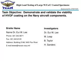
Briefer Name Name Dr. Eui W. Lee Phone: 301-342-8071 Fax: 301-342-8120 Address: Building 2188, NAS Pax River E-mail:leeew@navair.navy.mil. Investigators : Dr. Eui W. Lee M. Leap B. Taylor H. Sanders.

E N D
Briefer Name Name Dr. Eui W. Lee Phone: 301-342-8071 Fax: 301-342-8120 Address: Building 2188, NAS Pax River E-mail:leeew@navair.navy.mil Investigators: Dr. Eui W. Lee M. Leap B. Taylor H. Sanders Task Objective: Demonstrate and validate the viability of HVOF coating on the Navy aircraft components.
Thrusts • Fatigue and tensile samples for JTP are 1/4” diameter configuration • There are differences between small samples and real components in terms of coating characteristics -the ratio between the coating and sample thickness-impingement angle: small for the small samples
HVOF COATED TUBULAR FATIGUE SPECIMENS R = -1 HVOF 17 (3) DSP-1000 SPECIMEN a NO VISIBLE SPALLING STEPPED STRESS TESTS STARTED AT 150 ksi 220 ) i s k ( G N I 200 L L STEPPED STRESS TEST A SINGLE STRESS TEST P S E L 180 B I S I V R O F 160 S S E R T S 140 L A I X A 120 220 ) i s k ( G N I L L 200 A P S E L B I S I V 180 R O F S S E R T 160 S L A I X A 140 0.005 0.006 0.007 0.008 0.009 0.010 0.011 0.012 0.013 HVOF COATING THICKNESS (in.) HVOF COATED TUBULAR FATIGUE SPECIMENS R = -0.33 (2) b (2) NO VISIBLE (2) SPALLING STEPPED STRESS TESTS STARTED AT 160 ksi
HVOF COATED TUBULAR FATIGUE SPECIMENS R = -1 HVOF 17 (3) DSP-1000 SPECIMEN (2) a NO VISIBLE SPALLING HY TUF STEEL 220 ) i s k ( G N 200 I L STEPPED STRESS TEST L A SINGLE STRESS TEST P S E 180 L B I S I V R O 160 F S S E R T S 140 L A I X A 120 220 ) i s k ( G N I L 200 L A P S E L B I S I 180 V R O F S S E R 160 T S L A I X A 140 0.005 0.006 0.007 0.008 0.009 0.010 0.011 0.012 0.013 HVOF COATING THICKNESS (in.) HVOF COATED TUBULAR FATIGUE SPECIMENS R = -0.33 (2) b (2) NO VISIBLE (2) SPALLING HY TUF STEEL
Morphology of spalling exhibited by HVOF coatings in axial fatigue tests at R = -1: (a) specimen HVOF 8 (0.0055 in. coating), stepped stress test to 180 ksi and (b) specimen HVOF 4 (0.0055 in. coating), stepped stress test to 200 ksi (spalling failure near the end of the gage section) followed by testing at 210 ksi (spalling failure in the gage section).
Morphology of spalling exhibited by HVOF coatings in axial fatigue tests at R = -0.33: (a) specimen HVOF 7 (0.006 in. coating), stepped stress test to 190 ksi; (b) specimen HVOF 14 (0.009 in. coating), stepped stress test to 180 ksi, and; (c) specimen HVOF 30 (0.01225 in. coating) tested at 160 ksi. Arrows in (a) indicate regions of localized delamination and circumferential cracking (i.e., incipient spalling) in the gage section.