Analysis of Gossamer Space Structures Using Assumed Strain Formulation Solid Shell Elements
Analysis of Gossamer Space Structures Using Assumed Strain Formulation Solid Shell Elements. Keejoo Lee and Sung W. Lee Department of Aerospace Engineering University of Maryland College Park Gregory V. Clarke Goddard Space Flight Center 2002 FEMCI WORKSHOP. Motivation.

Analysis of Gossamer Space Structures Using Assumed Strain Formulation Solid Shell Elements
E N D
Presentation Transcript
Analysis of Gossamer Space Structures Using Assumed Strain Formulation Solid Shell Elements Keejoo Lee and Sung W. Lee Department of Aerospace Engineering University of Maryland College Park Gregory V. Clarke Goddard Space Flight Center 2002 FEMCI WORKSHOP
Motivation • Because of zero-gravity environments involved in conducting experiments, greater emphasis may be placed on computational analysis of gossamer space structures. • Length ( ~ 100 m) to thickness (~1 micron) ratios, L/t, are very large (~ L/t=108).
Objective • The purpose of this work is to investigate the applicability of assumed strain formulation solid shell elements to gossamer space structures. • Shell elements suffer from locking as thickness decreases – it is necessary to determine the range of L/t for which the assumed strain formulation solid shell elements perform with precision.
Solid Shell Formulation • Treats shells as 3-dimensional solids. • No rotational angles are used. - All kinematic variables are vectorial. - All kinematic variables are based on a global coordinate system. - Allows transverse shear deformation. - Stretchable in the thickness direction.
Assumed Strain Formulation • Assumed displacement formulation - Susceptible to element locking. • Assumed strain formulation - In addition to the assumed displacements, assumed strain field, independent of the assumed displacements, introduced to avoid element locking. - Assumed strain parameters eliminated at element level.
54 DOF Elements 18 Node Version 3 DOF/NODE 9 Node Version 6 DOF/NODE
Numerical Tests • To investigate the applicability of the assumed strain formulation solid shell elements to extremely thin structures under the following conditions: - Geometrically linear and nonlinear. - Linear elastic materials. - Static loadings .
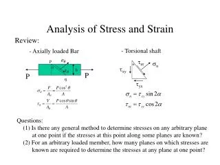
The Effect of Element Locking • Linear analysis of a beam under uniformly distributed load is carried out to appreciate the effect of element locking.
Modified Moduli • To increase the effective range of length/thickness ratio, one may introduce modified moduli for the beam as follows:
Excluding the contribution of membrane energy,the total strain energy U can be expressed as
For the transverse shear energy part, one may introduce modified shear modulus, as follows: Similarly, one may introduce modified Young’s modulus, corresponding to the thickness change as follows:
Quadruple Precision • One may numerically extend the effective range of length-to-thickness ratios using the quadruple precision. - Double precision ~ 15 decimal digits. - Quadruple precision ~ 30 decimal digits.
Wrinkling • Gossamer structures are susceptible to wrinkling. • To predict details of wrinkles such as shapes and amplitudes, one may use a dynamic scheme that includes the effect of mass and fictitious damping.
A Square Membrane P Material: Kapton (1) (2) Boundary Conditions - (1): u=0 - (2): v=w=0 (2) (1) P
A Square Membrane P 0.1P 0.1P P
Observations (1) • From the numerical tests, Max. L/t ranges are - Double precision w/o modification ~ 105 - Double precision with modification ~ 108 - Quadruple precision w/o modification ~ 1016 - Quadruple precision with modification ~ 1018
Observations(2) • The use of quadruple precision, combined with the modified moduli significantly increases the effective range of length-to-thickness ratios for assumed strain solid shell elements. • Also, it appears that the wrinkling formation of membranes can be simulated via a geometrically nonlinear analysis, incorporating the fictitious damping and initial geometrical imperfections.