Download
1 / 25
250 likes | 380 Views
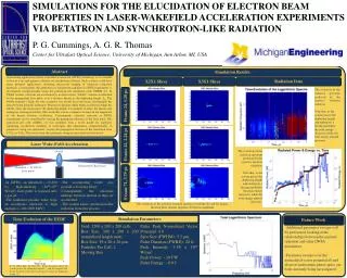
Investigation of fracture & fault populations in analogue outcrops for use in the Spindrift subsurface reservoir/fluid flow model. GetRichQuick Ltd. A.Anigboro, V. Carter, S. Green, R. Hall, P. Jones, G. Markham, M. Thomas. MSc. Structural Geology with Geophysics,

E N D
Investigation of fracture & fault populations in analogue outcrops for use in the Spindrift subsurface reservoir/fluid flow model. GetRichQuick Ltd. A.Anigboro, V. Carter, S. Green, R. Hall, P. Jones, G. Markham, M. Thomas. MSc. Structural Geology with Geophysics, Dept. Earth Sciences, University of Leeds.
Objective: “ Use of analogue data collected from outcrops at Flamborough Head for input into the Spindrift prospect subsurface fluid flow model.” Aims: Analysis of collected data in terms of; • Relationship of fracture spacing/density to bed thickness & vertical connectivity, • Lateral connectivity and orientation of fractures, • Stratigraphic controls on fault geometries & fault rock properties, • Fault throw, orientation, & clustering relationships, Assessment of all data in terms of predictability of fault & fracture populations permeability.
Fracture density • As bed thickness increases fracture spacing increases. • In smaller beds (<15cm) fracture spacing rarely exceeds 20cm. • In larger beds (>30cm and especially >50cm) fracture spacing reaches as high as 90cm. • The greater thickness gives the bed a higher competence, which results in the stress needed to form fractures being greater. • Data doesn’t account for fracture clustering around faults.
Fracture density • Trend visible suggesting most fractures fit a general rule. • 2/3 Bed Thickness + 20cm • Data set is not large enough for a definitive equation. • Data also suggests that larger beds show more fractures above the general trend.
Vertical Connectivity • Fractures do not show a tendency to cross from one bed to another. • Fractures that do cross from one bed to another are associated with faults. • Most beds show well developed Stylolites. • Stylolites appear to facilitate more pervasive fracturing. • Stylolites were formed before the vertical fractures. • Beds show well developed clay layers on their tops, which act as an inhibitor to vertical pervasiveness.
Plan Fracture connectivity • 6 x 1m2 quadrant samples taken from exposed bedding surfaces of several different units. • Digital photo mapping & field based measuring implemented in tandem. • Orientation, length & density (cumulative length per m2), average fracture length, & bedding thickness recorded. • Impact of faulting on fracture populations investigated.
Bed thickness – 0.25m • Fracture frequency - 53 • Cumulative fracture length per m2 - 11.27m • Average fracture length – 0.21m • Bed thickness – 0.35m • Fracture frequency - 245 • Cumulative fracture length per m2 - 21.74m • Average fracture length – 0.09m 10cm 10cm Loc. 1 Loc. 2 N N
Bed thickness – 0.18m • Fracture frequency - 128 • Cumulative fracture length per m2 - 14.96m • Average fracture length – 0.11m • Bed thickness – 0.30m • Fracture frequency - 227 • Cumulative fracture length per m2 - 21.53m • Average fracture length – 0.09m N N 10cm 10cm Loc. 3 Loc. 4 Faulting increases local fracture density Conjugate fault set intersecting in cliff face
Bed thickness – 0.25m • Fracture frequency - 19 • Cumulative fracture length per m2 - 7.95m • Average fracture length – 0.42m • Bed thickness – 0.75m • Fracture frequency - 17 • Cumulative fracture length per m2 - 5.77m • Average fracture length – 0.34m N N 10cm 10cm Loc. 5 Loc. 6
Bed thickness vs. Plan Fracture properties Cumulative length (m) per m2 vs. bed thickness (m) • Weak correlation between measures of plan fracture density and bed thickness; • Limited data set • Difficult to assess bed thickness Fracture frequencyvs. bed thickness (m) • Local fracture densities related to proximity to faulting
Plan Fracture orientations • Data collected from 6 x 1 m2 quadrants (~700 fractures) • Wide spread of fracture strike orientations, with 335-155 and 260-080 exhibiting dominant trends • Local fault orientations influence fracture density & orientations.
Observations from Plan fractures • Near 100% connectivity of joints/fractures • Connectivity independent of density of fractures/faulting • Increased local density of fracturing around faults • Density of fracturing is related to bed thickness, data collected from foreshore difficult to relate to bed thickness. • Plan densities should be correlated with cross-sectional data • Dominant trends of fractures related to mean fault orientations • Need to be correlated with fault orientations
Stratigraphic control of faulting • Strain taken up by weaker Marl beds. • Which often mark the tip of faults • Here they also provide a weak medium for fault propagation and linkage. • Some fault planes contain breccia and clay smears 4 metres
Fault geometry • Fault geometry is strongly linked to fracture orientation. • Flat geometry causes heavy fracturing, mostly in the Hanging-wall • This leads to fracturing along strike of the fault orientation.
Fault relationship with jointing /orientation Fault orientation. • Poles to planes and average great circle • Synthetic (left). Antithetic (right). Mean fault planes 332 / 53 North-east Mean fault planes 241 / 64 South-west
Throw vs transect length • Clustering of smaller faults around larger faults • Available data suggests larger faults (>15cm) appear approximately every 25m
Frequency of fault spacing • Median spacing of faults = 0.5 metres • Trend line fits exponential curve to 94%
Fault throw vs cumulative frequency • Higher frequency of small displacement faults • Low frequency of large displacement faults
Large scale faulting – examples of damage zone Main fault damage zone Calcite filled fractures/veins (mm-dm width) within the damage zone Significant reduction if fracture permeability Barrier to fluid flow Rotated, dragged & thrusted bedding Complex filled veins & fractures
Prediction of fracture & fault permeability • Little vertical connectivity of fractures (strata-bound >90%), • High degree of lateral connectivity along beds, • Higher density of fractures within thinner beds, • Small offset faults may provide vertical connectivity, • Larger offset faults may produce fault seal gouges/smears leading to potential compartmentalisation. • Large offset faults are likely to have a wide, complex damage zone • High density of damage around faults (eg. Compressional over steps/damage zones).
Uncertainty analysis • Data collection • Limited sample size • More data required over larger area • Measurement errors • Orientation of sample lines relative to trends of features • Upscaling • Do relationships found occur at all scales? • Use of analogue data set • Uplift induced fracturing, jointing & faulting • How ‘closed’ are fractures under subsurface pressure conditions.
Implications for reservoir production/development • Analogue data collection allows for greater understanding of potential reservoir production issues, ie fluid flow during production. • Interaction of fractures & small offset faulting creates high lateral permeability allowing efficient drainage of beds. • Very High fracture permeability parallel to small offset faults • Vertical restriction of fracture permeability & presence of marl units may prevent excessive water cut in wells. • Larger offset faults, if open may encourage water production, however complex low perm damage zone & fault gouge likely to create sealing faults. • Evaluation of seismic structure & understanding of sub-seismic features & populations is key to successful well planning & development.