Download

1 / 15
150 likes | 312 Views
1/14. Micro-discharge debug with CCD. Shuichi Shimma Univ. of Tsukuba. ATLAS Japan Silicon Group. (KEK, Tsukuba, Okayama, Hiroshima, Kyouto univ. of educ.). JPS meeting @ Tohoku Gakuin Univ. Mar. 29, 2003. Contents. Introduction for micro-discharge Setup

E N D
1/14 Micro-discharge debug with CCD Shuichi Shimma Univ. of Tsukuba ATLAS Japan Silicon Group (KEK, Tsukuba, Okayama, Hiroshima, Kyouto univ. of educ.) JPS meeting @ Tohoku Gakuin Univ. Mar. 29, 2003 Contents • Introduction for micro-discharge • Setup • I-V characteristics • Procedure of micro-discharge debugging • Results • Summary
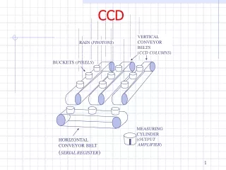
2/14 1. Introduction for micro-discharge Micro-discharge is caused by high electric field. edge design of electrode, bulk non-uniformity (defects), scratches on the silicon surface, etc. When the electric field becomes high, electron avalanche develops. In this situation, electron temperature becomes higher than lattice temperature. Hot electrons Using a cooled CCD camera, we can make images of infrared radiation from hot electrons. S. Shimma, JPS meeting @ Tohoku Gakuin Univ. : Mar. 29, 2003
3/14 2. Setup HPK digital CCD camera Specifications Effective area: 12.3mm x 12.3 mm Effective # of pixels: 512 (H) x 512 (V) Pixel size : 24 um x 24 um Read out noise : 12 electrons r.m.s Dark current : 3 electrons/pixel/sec @ -50degC A/D converter : 16 bit Spectral response characteristics We used, wide-angle lens, (covers ~½ of the module) microscope lens, (enlarged view up to 300 mm x 300 mm). S. Shimma, JPS meeting @ Tohoku Gakuin Univ. : Mar. 29, 2003
4/14 3. I-V characteristics Sample modules : 2022017020xxxx, from mass production (xxxx = 0069, 0099, 0100, 0101, 0102, 0106,0202) S. Shimma, JPS meeting @ Tohoku Gakuin Univ. : Mar. 29, 2003
5/14 4. Procedure of micro-discharge debugging [0] Choose a module with micro-discharge, [1] Take a picture in light, [2] Take a noise image, [3] Take a hot spot image applying HV up to 550 V, [4] Subtract noise from hot spot image ([3] – [2]), [5] Superimpose [4] on the [1] . 10 mins (wide-angle) Exposure time 1 to 3 mins (microscope) CCD temperature : -55degC S. Shimma, JPS meeting @ Tohoku Gakuin Univ. : Mar. 29, 2003
6/14 5. Results Modules 0069, 0101, 0102 and 0106. The cause of spots was sensor itself. 0069 (S1) 0101 (S1) 0102 (S1) 0106 (S4) 7.8 mA -> 5.6 mA 11 mA -> 7 mA 6.7 mA -> 4.5 mA 6.2 mA -> 3.5 mA Wide-angle view(upper), x125 magnification picture (lower) S. Shimma, JPS meeting @ Tohoku Gakuin Univ. : Mar. 29, 2003
5. Results (Cont’d) 7/14 Module 0100 Hot spot was observed on the sensor 4 (backside of the module). Enlarged 13 mA -> 11.3 mA (X 12.5 maginification) The cause of hot spot is investigated by the visual inspection. S. Shimma, JPS meeting @ Tohoku Gakuin Univ. : Mar. 29, 2003
8/14 5. Results (Cont’d) Visual inspection 0100 0106 Because of the contact, decay time of micro-discharge is longer. The cause of hot spot was a shave off a bonding wire. It was in contact with the surface of detector. S. Shimma, JPS meeting @ Tohoku Gakuin Univ. : Mar. 29, 2003
9/14 5. Results (Cont’d) Module 0099 Hot spot was observed on the sensor 1 (frontside of the module). 3.8 mA -> 2.4 mA (X 125 maginification) The initial I-V curve was good. After the long-term test, micro-discharge appeared. Two hot spots exists at the neighboring electrodes. S. Shimma, JPS meeting @ Tohoku Gakuin Univ. : Mar. 29, 2003
10/14 5. Results (Cont’d) Module 0202 (the worst I-V curve) (X 125 maginification) 31.2 mA -> 2.3 mA All sensors did not show any micro-discharge before module-assembly. Some problems occurred at module-assembly? S. Shimma, JPS meeting @ Tohoku Gakuin Univ. : Mar. 29, 2003
11/14 5. Results (visual inspection) (X 250 magnification) (X 375 magnification) No scratches were found around the hot spot. Instead, several black dots were found near the hot spot. S. Shimma, JPS meeting @ Tohoku Gakuin Univ. : Mar. 29, 2003
12/14 6. Summary We have started to locate micro-discharge points in series modules with the CCD camera. We examined 7 modules, their causes of microdischarge are; 0069 : 0101 : 0102 : 0106 : Sensor itself, (discharge appeared at sensor test.) 0100 : shave off bonding wire, 0099 : impurities (?), long-term applying HV, 0202 : dusts on the sensor surface. These modules can be used as the test modules. S. Shimma, JPS meeting @ Tohoku Gakuin Univ. : Mar. 29, 2003
Misc. To identify the spots, we set the HV power OFF, the power to ASICs from SCTLV OFF and VME power ON. We still found the luminous spots. The enlarged view of the luminous spot is … According to chip designer: “The luminous spot is due to a diode for the prevention of ESD. When the difference of potential between Vdd and Reset B is larger than 0.6 V, the diode starts working.” We measured the ResetB with a tester. ResetB = 1.5 V @ Vdd off X62.5 magnification
Misc. To confirm the function of ESD diode, we took pictures with Vdd = 4.0 V. ResetB = 4.5 V @ Vdd on (design value : 4.0 V) Previous spots disappeared. Other luminous spots were due to heat in the ASICs. Working correctly !!