Download
1 / 21
210 likes | 425 Views
BEPCII Cryogenic Control. Gang Li IHEP, Beijing ,China. Outline. Preamble Cryogenic control system Control system overview Exchanging data between S7-400 and IOC Control system of superconducting devices Commissioning Conclusion Acknowledge. Preamble.

E N D
BEPCII Cryogenic Control Gang Li IHEP, Beijing ,China
Outline • Preamble • Cryogenic control system • Control system overview • Exchanging data between S7-400 and IOC • Control system of superconducting devices • Commissioning • Conclusion • Acknowledge Shanghai EPICS Seminar,Mar12-15,2008
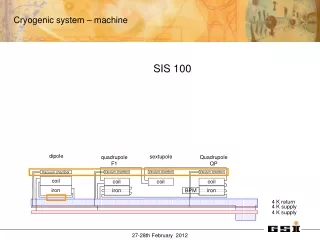
Preamble • In order to increase the luminosity of the BEPC, the project BEPCII was constructed. • Three kinds of superconducting devices are used: superconducting RF cavity (SRFC), superconducting solenoid magnet (SSM) and superconducting quadrupole magnet (SCQ). • The cryogenic system produce cooling helium for SRFC,SSM and SCQ. Shanghai EPICS Seminar,Mar12-15,2008
Preamble • Two 250W compressors are installed in cryogenic plant: One compressor for SRFC, the other for SSM and SCQ respectively. • The compressor system comprises a main compressor, a refrigerator, a subcooler and transfer lines. • Superconducting SRFC consists of two SRFCs, one valve box and one 2000L Dewar. • Superconducting magnets are composed of two SCQs, one SSM, three valve boxes and one 1000L Dewar. Shanghai EPICS Seminar,Mar12-15,2008
Preamble Cryo Plant Linac Transport Line Storage Ring Shanghai EPICS Seminar,Mar12-15,2008
Preamble Cryogenic Hall Shanghai EPICS Seminar,Mar12-15,2008
Preamble Cryo Control Room Tank Valve Box for SSM&SCQ Valve Box for SRFC Shanghai EPICS Seminar,Mar12-15,2008
Cryogenic control system • Control system overview • The cryogenic control system is divided into compressor control and superconducting control according to the front-end devices. • Two cryogenic compressor systems were purchased from the vendor-Linde Company, which performs the compressor control through S7-400 PLC, Profibus and WinCC software. • The control system of superconducting devices was developed by IHEP, using AB-PLCs, ControlNet and VME IOCs(See Fig1). Shanghai EPICS Seminar,Mar12-15,2008
Cryogenic control system • Control system overview Fig1 the cryogenic control structure of BEPCII project Shanghai EPICS Seminar,Mar12-15,2008
Cryogenic control system • Exchanging data between S7-400 and IOC • It is required to integrate the compressor signals into EPICS. • The open development kit (ODK) is a software package, which provides open C application program interface (C-API). • The data of WinCC can be accessed or changed by EPICS via C-API of the ODK (See Fig2). Fig2 the communication between S7-400 PLC and EPICS IOC Shanghai EPICS Seminar,Mar12-15,2008
Cryogenic control system • Control system of superconducting devices • The cryogenic control system supplies the 4.5k liquid helium to the SRFC, the 4.5k two-phase helium for SCQ and SSM of the BEPCII. • The cryogenic control system is expected to run continuously and steadily. • It is very important to design the control logic, control PID loops, the low level interlock and sequence. Shanghai EPICS Seminar,Mar12-15,2008
Cryogenic control system • Control system of superconducting devices • Design of Control Function (See Fig3) • The control logic and control loops often need to be modified during the commissioning stage. • Generally the loops running on the PLCs must work continuously, even momentary interruptions can not be tolerated. • A short interruptions can be tolerated in IOC side. • All high level control algorithms, control PID loops and automatic sequences reside in IOCs under the EPICS. • Only the low level interlocks and device I/O of the pivotal equipments run in PLCs. Shanghai EPICS Seminar,Mar12-15,2008
Cryogenic control system • Control system of superconducting devices • Design of Control Function Fig3 Design of Control Function of Superconducting Devices Shanghai EPICS Seminar,Mar12-15,2008
Cryogenic control system • Control system of superconducting devices • PID Control Loop • To keep the cryogenic system operation best with a fairly constant load, a lot of PID control loops are designed and used in cryogenic control system. • Here is the example which shows how to control the level of liquid helium in superconducting cavity (See Fig4). • The power of the electrical heater is used to compensate the dynamical load of the SRFC. • Two PID control loops are designed to keep the balance of the liquid level in vessels. Shanghai EPICS Seminar,Mar12-15,2008
Cryogenic control system • Control system of superconducting devices • PID Control Loop • The output power formula: PHeater=PState+PRF+PPID • PState stands for static state power of electrical heater. • PRF means dynamic load power from RF system. • PPID is compensating power of electrical heater. • SetpL_H and SetpL_V stand for the setpoint value of the level-heater and the level-valve PID control loop respectively. Fig4 Two PID Control Loops Shanghai EPICS Seminar,Mar12-15,2008
Cryogenic control system • Control system of superconducting devices • Interlocks in the PLC • In order to protect the key devices from damage, a lot of interlock conditions need to be taken into account to force actuators at a safe position. • All interlock actions are performed automatically as soon as one of interlock conditions is available. • The recovery of the interlock status must be enabled by the operator. • Of course, these interlock programs reside in the PLC, which is independent from the IOC. Shanghai EPICS Seminar,Mar12-15,2008
Cryogenic control system • Commissioning of the cryogenic control system Control Crates Shanghai EPICS Seminar,Mar12-15,2008
Cryogenic control system • Commissioning of the cryogenic control system Shanghai EPICS Seminar,Mar12-15,2008
Cryogenic control system • Commissioning of the cryogenic control system Cryogenic control OPI Shanghai EPICS Seminar,Mar12-15,2008
Conclusion • Two-layer control structure is adopted in cryogenic system. • The high level control is on the EPICS IOC, where all control algorithms, PID control loops and sequences reside. • The low level control is on the PLC, which performs data input output and the important and necessary interlocks. • The control system of SRFC has been in operation for more than one and a half years without any problem. • The improved cryogenic control system was put into operation in May 2007 and it is working well. Shanghai EPICS Seminar,Mar12-15,2008
Acknowledge • The control system of superconducting systems was designed, constructed and is commissioning successfully at BEPCII. • We wish to express our gratitude to Mr. Matthias Clausen from DESY, who has given us a lot of valuable advice and help. • We would also like to thank the cryogenic group at IHEP for their skillful work and assistance during the commissioning of the cryogenic control system. Shanghai EPICS Seminar,Mar12-15,2008