Download
1 / 18
180 likes | 194 Views
Learn about the KEK EP recipe for cleaning and maintaining 9-cell cavities, including flow rates, current density, and voltage parameters. Discover the steps involved in the EP process and the use of different rinsing techniques to reduce sulfur contamination.

E N D
Standard EP recipe at KEK T. Saeki KEK Hot topics session SRF2011 25 – 29 July 2011, Chicago
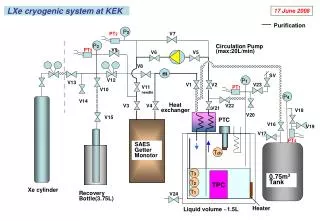
EP facility at STF/KEK Automatic Operation Console EP bed 9-cell cavity 1st floor 2nd floor New EP facility at KEK was constructed in 2008, instead of old Nomura EP facility, which was closed in the summer of 2009. EP solution reservoir tank
The KEK recipe by Kenji SAITO from TRISTAN age. Current density = 50 mA/cm2 We had been keeping the KEK recipe established by Kenji SAITO in TRISTAN age. Current density = 50 mA/cm2 Slide from Lecture @ Nagoya Univ. by K. Saito
Difference between Jlab and KEKNovember 2009 Related to nice results of JLab? => Now, EP current density (Final EP) = 30 – 40 mA/cm2 at KEK Yield rate for ILC threshold of VT (35 MV/m): 50% for recent 6 MHI cavities(1 bad cavity with only 1st VT).
EP2 (finial 20um) Recipe at KEK Flow rate of EP electrolyte:15L/min.Current density:30- 40mA/cm2 (Current ~200A), Voltage=15-22 VCavity rotation speed:1rpmCooling: Air cooling (Outer surface of cavity<350C) After EP voltage turned off (V=0).EP electrolyte rinse with cavity rotation: 3rpm. 20min.Draining of EP electrolyte Vertical position: 5min.Horizontal position: 2min. Vertical position: 2min. (Purging with N2 gas) UPW filling and draining (rinse)UPW+PW(flow rate : 25-27 L/min) with vibrator Water should reach the top of cavity for20min.Additional PW running rinse reaching top of cavity (20L/min) with vibratorSub-total, 60min.PWFilling 10min. Draining 3min.Repeatfor 30min.Total90min. Disassembly of setup and low pressure UPW rinseFlange and HOM cap/antenna, beam-pipes: Brushing with 2% FM-20 detergentDetergent rinse of cavity with 2% FM-20 at 50 0C (60 min.)Disassembly and low pressure UPW rinse and HPR
EP1(bulk 100um) recipe at KEK Flow rate of EPelectrolyte:15L/min.Current density:45- 50mA/cm2, Voltage=18-22 V Cavity rotation:1rpmCooling: Air cooling After V=0EP electrolyte rinse with cavity rotation: 3rpm. 20min.Draining of EP electrolyteVertical position 5min.Horizontal position 2min. Vertical position 2min. (Purging with N2gas) UPW Filling10min.Draining 3min.Repeat for60min.Disassembly and low pressure UPW rinse Detergent rinse2%FM-20 at 50 0C for 60min.Disassembly of setup and HPR SettingHPR
EP parameters at KEK (June 2010 – July 2011) Final EP (~20 um) for 9-cell cavities Current density = 30 – 40 mA/cm2 T of acid inside cavity = 23 – 31 0C Voltage = 15 – 22 V Nb concentration (g/L)
EP parameters at KEK (June 2010 – July 2011) Bulk EP (~100 um) for 9-cell cavities Current density = 45 – 50 mA/cm2 T of acid inside cavity = 30 – 40 0C Voltage = 18 – 22 V Nb concentration (g/L)
EP with Nb sample in laboratory Labo-EP setup at KEK Bolt to connect shaft and Al plate Moving shaft Aluminum plate covered by Teflon tape Aluminum cathode Nb sample anode EP acid Bolt to connect Nb sample and Al plate
TEST OF LOW VOLTAGE EP (5V) AT SACLAY TO REDUCE SULFUR CONTAMINATION = Theoretical way to reduce Sulfur Contamination (investigation ongoing) Reduction Reactions at the Cathode Reduction of H+: 2 H+ + 2 e-→ H2 (Predominant) Reduction of SO42-: SO42- + 8H+ + 6e- → S + 4H2O Does a cathodic overpotential lead to an increased sulfur generation? →Two Niobium samples electro-polished at 5V and 20V for a similar heavy removal with 1-9-1 (HF-H2SO4-H2O) Mixture Sample A, 20 Volts: 9.18g removed 51 hours EP Sample B, 5 Volts: 9.11g removed 115 hours EP Experiment at Saclay Slide by F. Eozenou
TEST OF LOW VOLTAGE EP (5V) TO REDUCE SULFUR CONTAMINATION SULFUR FOUND IN THE EP MIXTURE (200mL) AFTER TREATMENTS OF SAMPLES A AND B. SULFUR EXTRACTED WITH CHLOROFORM: Experiment at Saclay Slide by F. Eozenou
Rinse Effect to Remove Sulfur precipitation/contamination Teflon texture Before rinse Many white dots are sulfur contamination U.P.W. ultrasonic rinse Ethanol ultrasonic rinse FM-550 (>10%) rinse After rinse Sulfur removed Sulfur removed 10
Results of rinse effect tests • Test of FM-20 (LION detergent) and 10% H2O2 • Test of Ethanol and FM-550 (LION detergent) 11
JLab Nb sample with artificial pits Pit3 40 um BCP (30um) As received EP (30um) Large steps at grain-boundaries after BCP. EP (120um) EP (90um) EP (60um) After BCP(30um)+EP(120um), still the edge of pit is sharp! 9
EP with Nb sample in laboratory Labo-EP setup at KEK Bolt to connect shaft and Al plate Moving shaft Aluminum plate covered by Teflon tape Aluminum cathode Nb sample anode EP acid Bolt to connect Nb sample and Al plate