Download
1 / 21
210 likes | 520 Views
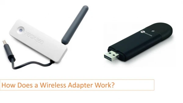
Wireless Power Adapter for Rechargeable Devices. Group 4 Joe Sukk.ar Peter Hans Hirschboeck April 28, 2006. Introduction. We wanted to build a wireless changing adapter to act the same as an ac/dc power adapter

E N D
Wireless Power Adapter for Rechargeable Devices Group 4 Joe Sukk.ar Peter Hans Hirschboeck April 28, 2006
Introduction • We wanted to build a wireless changing adapter to act the same as an ac/dc power adapter • This process is called inductive charging because the mechanisms to transfer the power are transformers/inductors
Principles of Operation • The base unit inductor and receiving inductor form a two part transformer • When the receiving unit is placed on the base unit, the transformer is complete, and power can transfer.
Physics Behind Design • When time varying current passes through the primary coil, it creates a magnetic field • The inverse occurs on the secondary side, where the magnetic field induces an electric field in the coil • When the device completes the secondary charging circuit, this field creates the necessary voltage and current to charge the device
Major Modules • DC/AC converter • Split-core transformer • Transmitting inductor • Receiving inductor • Rectifier and filter • Voltage regulation
Block Diagram Consists of two major parts Base Unit Portable Device Side
DC/AC Converter DC Link provided PWM/Gate Driver Dual MOSFETs
Transformer Effectively Doubles Voltage Several Redesigns Ferrite Core
Transmitting Inductor Transmits wireless power
Receiving Inductor Minimize Size
Rectification and Filter Converts AC Signal to DC Full Bridge Can be significantly shrunk down in size
Voltage Regulation Provides constant 5V to device Linear
Performance • Device operates as designed • Safe, regulated 5V signal to device • Up to --- output to device • Wall charger outputs 300-500mA • Power usage • --- Watts when idle • --- Watts when charging • Efficiency • Our unit operates with up to --% efficiency • Wall charger operates with ~40% efficiency
Areas of Improvement • Utilize switch mode converters instead of linear regulators • Incorporate RFID instead of magnetically tripped switch • Shrink the secondary packaging to fit internally
Marketability • Battery pack retrofit kits • Secondary side integrated into battery pack • Replace OEM charge regulation with more appropriate customized algorithm • Control loop to maximize power transfer
Ethical Considerations • There are no major ethical concerns • We did not investigate FCC compliance concerning interference with other devices
Special Thanks • Professor Krein • Jonathan Kimball • Dwayne Hagerman