Analog Electronics Workshop Filtering
Analog Electronics Workshop Filtering. March 13, 2013. A filter’s purpose in life. is to… Obtain desired amplitude versus frequency characteristics or Introduce a purposeful phase-shift versus frequency response or Introduce a specific time-delay (delay equalizer).

Analog Electronics Workshop Filtering
E N D
Presentation Transcript
Analog Electronics WorkshopFiltering March 13, 2013
A filter’s purpose in life is to… Obtain desired amplitude versus frequency characteristics or Introduce a purposeful phase-shift versus frequency response or Introduce a specific time-delay (delay equalizer)
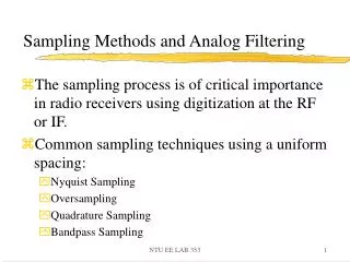
Common filter applications Band limiting filter in a noise reduction application
Filter Types Low-pass High-pass Band-pass Band-stop, or band-reject All-pass Common filters employed in analog electronics
Filter Types Low-pass High-pass fc fc A low-pass filter has a single pass-band up to a cutoff frequency, fc and the bandwidth is equal to fc A high-pass filter has a single stop-band 0<f<fc, and pass-band f >fc Band-stop Band-pass fl fh fl fh A band-stop (band-reject) filter is one with a stop-band fl<f<fh and two pass-bands 0<f<fl and f >fh A band-pass filter has one pass-band, between two cutoff frequencies fl andfh>fl, and two stop-bands 0<f<fland f >fh. The bandwidth = fh-fl
Filter Ordergain vs. frequency behavior for different low-pass filter orders Pass-band Stop-band fC(-3dB) 1kHz typically, one active filter stage is required for each 2nd-order function
Filter ReponsesCommon active low-pass filters - amplitude vs. frequency Δ attenuation of nearly 30 dB at 1 decade
Why Active Filters? Inductor size, weight and cost for low frequency LC filters are often prohibitive Magnetic coupling by inductors can be a problem Active filters offer small size, low cost and are comprised of op-amps, resistors and capacitors Active filter R and C values can be scaled to meet electrical or physical size needs A comparison of a 1kHz passive and active 2nd-order, low-pass filter
Two popular single op-amp active filter topologies2nd-order implementations Multiple Feedback (MFB) low-pass • supports common low-pass, high-pass and band-pass filter responses • inverting configuration • 5 passive components + 1 op-amp per stage • low dependency on op-amp ac gain-bandwidth to assure filter response • Q and fnhave low sensitivity to R and C values • maximum Q of 10 for moderate gains Sallen-Key (SK) low-pass • supports common low-pass, high-pass and band-pass filter responses • non-inverting configuration • 4-6 passive components + 1 op-amp per stage • high dependency on op-amp ac gain-bandwidth to assure filter response • Q is sensitive to R and C values • maximum Q approaches 25 for moderate gains
Active filter synthesis programsto the rescue! Modern filter synthesis programs make filter development fast and easy to use; no calculations, tables, or nomograms required They may provide low-pass, high-pass, band-pass, band-reject and all-pass responses Active filter synthesis programs such as FilterPro V3.1 and Webench Active Filter Designer (beta) are available for free, from Texas Instruments All you need to provide are the filter pass-band and stop-band requirements, and gain requirements The programs automatically determine the filter order required to meet the stop-band requirements FilterPro provides Sallen-Key (SK), Multiple Feedback (MFB) and differential MFB topologies; the Webench program features the SK and MFB Commercially available programs such as Filter Wiz Pro provide additional, multi-amplifier topologies suitable for low sensitivity, and/or high-gain, high-Q filters
The operational-amplifier gain-bandwidth requirements TI’ s FilterPro calculates each filter section’s Gain-Bandwidth Product (GBW) from: GBWsection = G ∙ fn ∙ Q ∙ 100 where: G is the section closed-loop gain (V/V) fn is the section natural frequency Q is stage quality factor (Q = 1/2ζ) 100 (40 dB) is a loop gain factor
The operational-amplifier gain-bandwidth requirement an example of the FilterPro estimation Let FilterPro estimate the minimum GBW for a 5th-order, 10 kHz (fc) low-pass filter having a Chebyshev response, 2 V/V gain and a 3 dB pass-band ripple FilterPro’s GBW estimation for the worst-case stage yields: GBW = G ∙ fn ∙ Q ∙ 100 GBW = (2V/V)(10kHz)(8.82)(100) = 17.64MHz vs. 16.94 MHz from the precise determination – see Appendix for details
Operational amplifier gain-bandwidth effectsthe Sallen-Key topology Op-amp fH Hz dB OPA170 90 k -21.8 OPA314 110 k -23.5 OPA340 260k -38.1 OPA140 428 k -44.3 FilterPro GBW 7.1 MHz The operational amplifier gain-bandwidth (GBW) affects the close-in response It also affects the ultimate attenuation at high frequency
Operational amplifier gain-bandwidth effectsthe Multiple Feedback (MFB) topology • The MFB shows much less GBW dependency than the SK • Close-in response shows little effect • Insufficient GBW affects the roll-off at high frequencies • The lowest GBW device (1.2 MHz) produces a gain deviation about 50-60 dB down on the response • A GBW ≥ 7 MHz for this example provides near ideal roll-off
Achieving optimum active filter performance Capacitors • Use quality C0G or film dielectric for low distortion • Type C0G has a low temperature coefficient (±20 ppm) • Lower tolerance, 1-2%, assures more accurate response • Higher order filters require ever lower tolerances for accurate response Signal source • Zs→ 0 Ω • An op-amp driver with low closed-loop gain often provides a low source impedance • Resistors • Use quality, low tolerance resistors • 1 % and 0.1% reduce filter sensitivity • Lower tolerance assures more accurate response • Low temperature coefficient reduces response change with temperature • Higher order filters require ever lower tolerances for accurate response • Operational Amplifier • Use required GBW - especially for the Sallen-Key • Be sure to consider the amplifier noise • High Zo effects can distort response • Higher amplifier current often equates to lower Zo and wider GBW • Consider dc specifications – especially bias current
Filtering Lab • FilterPro • Simulation • Measurement
8.0 Goal of Filter Lab • Use Filter Pro to design a Sallen-Key and Multiple Feedback filter • Simulate Sallen Key and Multiple Feedback filters using OPA170 and OPA241 • Sallen Key more sensitive to low GBW. • MFB less sensitive to low GBW. • OPA170, GBW = 1.2MHz • OPA241, GBW = 35kHz • Measure Sallen Key and Multiple feedback filters with both op-amps. • Demonstrate that MFB is less sensative then Sallen Key (both measured and simulated)
8.4 Hardware Setup Set both sets of jumpers to S-K to test the Sallen-Key configuration and to MFB for Multiple Feedback. Insert OPA170 into the socket and test both Multiple Feedback and Sallen –Key.
Ex 8.4: Instrument Setup The instrument setup above can be used for all the active filter measurements. Use the cursors to determine the cutoff frequency (-3dB point). In this example