Download
1 / 22
220 likes | 329 Views
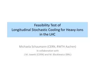
Feasibility Test of Longitudinal Stochastic Cooling for Heavy-Ions in the LHC. Michaela Schaumann (CERN, RWTH Aachen) In collaboration with J.M . Jowett (CERN) and M. Blaskiewicz (BNL). The Idea. Install reduced longitudinal stochastic cooling system in the LHC (IR4) using

E N D
Feasibility Test of Longitudinal Stochastic Cooling for Heavy-Ionsin the LHC Michaela Schaumann (CERN, RWTH Aachen) In collaboration with J.M. Jowett (CERN) and M. Blaskiewicz (BNL)
The Idea • Install reduced longitudinal stochastic coolingsystem in the LHC (IR4) using • existing Schottky Pickups at 4.8GHz, • only 1 longitudinal cavity at 4.8GHz resonant frequency, • + other required equipment (see later). • Coola low intensity Pb-test-bunch and observe the bunch length reduction over time. • Parasitic experiment: • Long commissioning time required! • Gate on particular bunch in filling pattern. • Take data for every fill. M. Schaumann
Tunnel Equipment in IR4 B1 B2 339m 58m 253m IP4 s from IP1 To avoid cross-talk between pickup and kicker chose max. separation! Max. equipment separation B2: 60m B1: 340m Note: B1H Schottky pickup gave best signals in the past. Schottky Pickups Potential Cavity Locations M. Schaumann
Signal Processing and Transportation in Tunnel at Surface S Signal Processing M. Schaumann
Required Hardware 54km cable Schottky Pickup at 4.8GHz operated in sum-mode (Transversal filter) E/O - Transformation to optical signal Light amplification Optical cable -Signal transportation to cavity location Notch filter (1-turn-delay, combiner and transformation to electrical signal) Narrow band-pass filter at 4.8GHz centre frequency Spectrum and Network analysers I/Q modulator for phase and amplitude adjustment Coaxial cable to power amplifier Power amplifier Cavity M. Schaumann
Experiment Setup • Low intensity bunch for fast cooling. • Non-colliding bunch for clear signal. • Non-cooled witness bunch for reference: • At 6.5Z TeV bunch length naturally shrinks due to radiation damping. • To distinguish between cooled and non-cooled bunches the cooling rate must be faster than the radiation damping rate! M. Schaumann
Experiment Setup Pilot/First bunch of 1st Train Additional Low Intensity Bunch • Bunch with lowest intensity in filling scheme. • If spacing to neighbouring bunches is to small, neighbours might be disturbed by cooling. • Intensity can be chosen to enhance cooling. • No disturbances for other bunches. • Easy to add witness bunch was equal properties. Flat Top Flat Top Injection Injection • Injection of first bunch just before abort gap. • Over-inject with the last train – no change of filling scheme necessary. • Only 30min observation. • Modify injection scheme! -Potential reduction of total bunch number. • Fill length for observation. Bunch with longest possible observation time. Only 30min observation. • Colliding! Non-colliding bunch would show cleaner signal. • Fill length for observation. M. Schaumann
Simulations • Test Bunch Parameters: • Enhanced cooling for long low intensity bunches • ions per bunch • = 12.5cm • Cooling efficiency depends on cooling system settings and available kick strength. • Too high amplification can lead to instabilities. • Kicker voltage is limited by available power. • Measurement of the FWHM is used to monitor the bunch length in LHC. M. Schaumann
Cooling Simulation at Flat Top FWHM 2) Fixed gain FWHM 3) Limited Voltage FWHM 1) No Voltage limit = 5kV & gain = 50e7 • Find best settings - scan over cooling gains: • No further improvement of cooling rate for gains > 300e7. • Voltage restrictions - scan over • At least 5kV are required to get a sufficient cooling rate. • Effect on FWHM is still small. • Best Settings for = 5kV– scan gains: • Bunches split up in two groups: • Inefficient cooling: almost no change to non-cooled bunch • Efficient cooling : for gains > 50e7 all bunches have equal cooling rate. M. Schaumann
Cooling Simulation at Injection FWHM 1) No Voltage limit FWHM 3) Limited Voltage FWHM 2) Fixed gain = 5kV & gain = 50e7 & fast and clear effect • Find best settings - scan over cooling gains: • Splitting into two groups with clear and fast observation of cooling. • No further improvement of cooling rate for gains > 100e7. • Voltage restrictions - scan over • 2kV show small cooling effect already. • 5kV are required to get a sufficient cooling rate. • Best settings for = 5kV – scan gains: • Bunches split up in two groups: • Inefficient cooling: almost no change to non-cooled bunch • Efficient cooling : for gains > 50e7 all bunches have equal cooling rate. M. Schaumann
Summary • Cooling of 1 low intensity bunch in B1 is proposed. • Using B1H Schottky pickup in sum-mode. • Install longitudinal cavity in one of the BQK.B1 positions. • As parasiticproof of principle experiment: • Inject additional very low intensity bunch close to the abort gap at the beginning of the injection process. • Observe cooling while the machine is being filled. • Over-inject the cooled bunch with the last injected train before going into the ramp. • Hardware requires mostly standard installations. • Signal processing, filters, cabling, amplifiers,… • Pickup already exists and able to be operated in requested mode. • Preliminary cavity design already available. • Highest cost contribution expected from cavity, power amplifier, spectrum and network analysers. M. Schaumann
Open Questions • Operate Schottky pickup in sum mode • Signal quality for ions? • Microwave background from injection of next train? • Signal processing: • Transversal filter? • Signal transportation: • Dispersion in 227km optical cable? • Spectral width of signal? • Can we broaden system bandwidth? • Detection limit of intensity for beam instrumentation? • How low in intensity can we go? • Cavity design (Filling time, voltage, power amplifier) • Excited frequencies must be cut off in cavity beam pipes. • … M. Schaumann
Acknowledgments M. Brennen, K. Mernick, S. Verdu Andres (BNL) M. Schaumann
Back-up M. Schaumann
Longitudinal Stochastic Cooling Principle - Particle Position at Particle Position at Average of pos. at Average of pos. at Pickup Signal Notch-Filter Kicker Measure average arrival time of particle samples Beam Difference in relative arrival time in consecutive turns due to momentum spread: Above transition: requires Kick = 0 requires Kick < 0 requires Kick > 0 kick M. Schaumann
Propagation Distance M. Schaumann
First Preliminary Cavity Design S. Verdu Andres (BNL) • Resonant freq. = 4.8 GHz • Kick voltage V = 3 kV (RMS?) • Power consumption P = 38 W • filling Time = 111 ns • loaded Q = 1680 • R/Q = 142 Ohm • Inner radius r = 20 mm • Length L = 120 mm • … M. Schaumann
Cooling System Commissioning and Operation • Measure resonant frequency of the cavity: • If necessary adjust by changing temperature with heaters. • Could be done without beam. • Check (beam) positions of pickup and cavity: • Beam should be centred in pickup and cavity to achieve best signal, max. kick and avoid beam losses. • Move pickup plates as close to the beam as possible to enhance signal. • Optimise delays and signal positions: • Centre revolution line in pickup signal. • Adjust 1-turn-delay of Notch-filter to get optimal difference signal (for correct amount and sign of kick). • Measure reference BTFs and adjust amplitude and phase of the kick with the I/Q modulator. • Repeat BTF measurement and adjustment from time to time during the experiment to ensure optimal cooling. • Cavity will be not available for cooling during the BTF measurement. M. Schaumann
Cooling Simulation at Flat Top = 5kV & gain = 50e7 • Scan over cooling gains: • No further improvement of cooling rate for gains > 300e7. • Scan over • At least 5kV are required to get a sufficient cooling rate. • Effect on FWHM is still small. • Scan over gains with = 5kV: • Bunches split up in two groups: • Inefficient cooling: almost no change to non-cooled bunch • Efficient cooling : for gains > 50e7 all bunches have equal cooling rate. M. Schaumann
Cooling Simulation Flat Top – short bunches M. Schaumann
Cooling Simulation at Injection = 5kV & gain = 50e7 & fast and clear effect • Scan over cooling gains: • Splitting into two groups with clear and fast observation of cooling. • No further improvement of cooling rate for gains > 100e7. • Scan over • 2kV show small cooling effect already. • 5kV are required to get a sufficient cooling rate. • Scan over gains with = 5kV: • Bunches split up in two groups: • Inefficient cooling: almost no change to non-cooled bunch • Efficient cooling : for gains > 50e7 all bunches have equal cooling rate. M. Schaumann
Cooling Simulation Injection – short bunches M. Schaumann