Download
1 / 49
490 likes | 697 Views
AN OVERVIEW MAKING IT IN ELECTRONICS Part 1. CHAPTER 1. OBJECTIVES In this chapter you will learn How an electronics design and fabrication experience can enhance skill level in a traditional "lecture and laboratory" classroom. Just what it is that electronics technicians do.

E N D
AN OVERVIEW MAKING IT IN ELECTRONICSPart 1 CHAPTER 1 CHAPTER 1
OBJECTIVES In this chapter you will learn • How an electronics design and fabrication experience can enhance skill level in a traditional "lecture and laboratory" classroom. • Just what it is that electronics technicians do. • About a career path for technicians with fabrication experience. • What the five-stage design and fabrication process is all about. • How the three-tier project approach provides maximum flexibility for project design and fabrication. • How the drawings and written documentation come together in the Project Report. • What traditional drafting tools are required for making the 10-drawing set contained in the Project Report. • How CAD has replaced traditional drafting equipment. • What tools are necessary for the mechanical and electrical fabrication of the prototype projects. CHAPTER 1
THE NEED FOR AN ELECTRONICS DESIGN AND FABRICATION EXPERIENCE In order to appreciate why, as future electronics technicians, you need to have an electronics design and fabrication background, let's examine briefly just what it is that technicians do. Let's see how the familiar "learning by doing" concept fits nicely into the activities that lie ahead and examine a most interesting career path, that of fabrication technologist. CHAPTER 1
WHAT ELECTRONICS TECHNICIANS ACTUALLY DO Electronics technicians build, repair, test, modify, and install electronic devices and equipment. That is, they do electronics fabrication. They are a hand-on group. If electronic theory is your overriding interest, perhaps you should strive to be an engineer rather than a technician. But if you want to "do" as well as "know" produce with your hands as well as your head, then working with the actual hardware is where you need to be. A soldering iron, along with a hand calculator, will be an important tool. CHAPTER 1
LEARNING BY DOING If your background in electronics is limited, or if the field is new to you, you may be reluctant to plunge right into electronics design and fabrication. Don't be Learning by doing is not hard; in fact, it can be downright enjoyable. Think a moment. You probably got interested in electronics because it seemed like a field in which you could get paid for doing the fun and interesting things you always wanted to do. If you have been an electronics hobbyist or enthusiast for some time, you are already familiar with the basics of electronics fabrication and are that much farther ahead. If signing up for an electronics course is your first experience, don't worry; this subject will show you all you need to know to get started. CHAPTER 1
FABRICATION TECHNOLOGIST Ordinarily, the electronics technician is expected to do it all: installation, maintenance, testing, troubleshooting, repair, and prototyping. Whether in medical, communications, industrial, computer, military, or consumer electronics, the technician deals with all aspects of the equipment, except perhaps its initial design. This is particularly true, for instance, with regard to troubleshooting and repair, two areas that are often seen as merging into one. Until recently, if you could find the problem (diagnosis), repair was just a simple follow-up: grab some solder, a soldering iron, a couple of additional hand tools, and the repair was quick and easy. With just a little training almost anyone could do it! CHAPTER 1
THE ELECTRONICS DESIGN AND FABRICATION PROCESS Let's examine the five stages of electronics design and fabrication, from thought to finished project, and see how these stages are covered in the book. Keep in mind that when you have completed the process involved, you will have both a finished prototype project and a completed Project Report CHAPTER 1
FROM THOUGHT TO FINISHED PROTOTYPE:A FIVE-STAGE PROCESS This subject explores the five stages required to design and fabricate a working prototype project: Design; drawing; experimenting; prototyping; and testing troubleshooting, and final documentation. CHAPTER 1
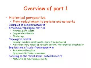
DOING IT ALL: FROM DESIGN TO DOCUMENTATION Figure 1 illustrates the five-stage design and fabrication process and how it relates to the written and graphics documentation of the project at each stage, the project progresses, as does the documentation for it. The figure also gives the individual chapters in which these stages are discussed. CHAPTER 1
Figure 1:Five-Stage electronics design and fabrication process to produce a working prototype and project report CHAPTER 1
FIVE STAGES-SEVEN CHAPTERS 1. Design Stage: In addition to reviewing basic electronic principles, introduces concepts of electronics design and looks at how we think up problems to be solved. An Overview-Making It in Electronics 2. Drawing Stage: Introduces an important language of engineering the drawing and examines the 10-drawing set that you will develop throughout the subject. The working schematic is also produced at this stage. 3. Experimenting Stage: The different methods used to assemble projects in order to test out their design are studied. Various experimenting systems are reviewed. CHAPTER 1
4. Prototyping Stage: Cover the design and manufacture of printed circuit boards. It deals with printed circuit board assembly, project packaging, and final assembly. 5. Testing, Troubleshooting, and Final Documentation Stage Here, the testing and troubleshooting of the completed prototype project are investigated. Preliminary testing and troubleshooting, at the project experimentation level, will already have taken place. Also, here is where all the necessary documentation that has been produced in the appropriate chapters is pulled together in the final Project Report. CHAPTER 1
PROJECT REPORT Along with actually fabricating a project, you must produce the proper documentation. It is true that for the Variable Power Supply Project, a complete documentation is already provided but to gain the full benefit and experience in the design and fabrication process, you will need to complete the appropriate graphics and written documentation, regardless of which project you construct. With respect to drawings, you can simply redo the 10-drawing set for the sample project. With the exercise project, you can copy the drawings from the project report, preferably, draw your own set. If you choose a project from the elective projects group, however, you will have to produce all but the design drawings yourself. CHAPTER 1
In addition to the graphics documentation, the project report requires written certification in the form of concepts and requirements, experiment results, test results, and summary and recommendations documents. such paperwork is not extensive; in some cases just a page or two is all that is needed; however, it must be done, and it must be concise and complete. If all this sounds a bit like work, well, it is; but when you bring that completed project, along with its Project Report, to your first job interview, you will know it has all been worthwhile. CHAPTER 1
TOOLS OF THE TRADE: ON THE BOARD The tools needed to design an electronic project are of two types: Traditional and computer-based. With the former, often referred to as drafting tools, or board tools, any of the drawings in the 10-drawing set can be made. In this section we list each traditional drafting tool needed and explain what it does. Discussion of tool use, however, comes later, in chapters where the applicable drawing procedure is described. CHAPTER 1
TOOLS OF THE TRADE: AT THE COMPUTER In creating a prototype project there is a design stage and a drafting stage. In design, new ideas are formulated; in drafting, these ideas are documented on paper in the form of drawings. Computers can help with both phases. With a sophisticated CAD (known both as computer-aided design and computer-aided drafting) system, every drawing in the project report can be entirely produced with the aid of a computer. Let's see what CAD is and then examine the computer hardware necessary to produce computer generated drawings. CHAPTER 1
TOOLS OF THE TRADE: ON THE BENCH Like tools for the drawing board, tools for the workbench must be chosen for their quality. As a working technician, you will be judged by the tools you keep. Your reputation is at stake; select tools that will give you pride of ownership. In this section the workbench and the tools for mechanical and electrical assembly that go with it are examined. The basic instruments needed to test and troubleshoot electronic projects are briefly introduced. (Additional tools and equipment, necessary to work with surface mount devices, are discussed in the following chapter). CHAPTER 1
TOOLS FOR ELECTRICAL WORK Tools for use in electrical work are needed to secure connections between conductors. Because most connections are still made with solder, soldering and disordering equipment is emphasized in this book. Nonetheless, wire-wrapping materials and solder less circuit boards ( breadboards) are also explored. CHAPTER 1
SUMMARY In this chapter part I, we have discussed the traditional electronics course and how the lecture and lab approach to learning can be supplemented with an electronics fabrication experience. By examining just what it is electronics technicians do, we gained an appreciation of the need for learning how to design, build, troubleshoot, and document a complete prototype project. Next, we investigated the five-stage design and fabrication process by probing the features of the • design; (2) drawing; (3) experimenting; (4) prototyping; and (5) testing, troubleshooting, and final documentation stages. We then saw how this book is structured around those five stages. We discussed the project building experience and looked into the project report, a summary containing all the necessary written and graphics documentation for the prototype project. CHAPTER 1
We explored the tools of the trade, on the board, at the computer, and on the bench. We examined the drafting table, along with the materials that go with it. We described the basic equipment necessary to make schematic and assembly drawings, as well as what is needed to produce the design layout and artwork for printed circuit board fabrication. We probed the outlines of a computer-aided design (CAD) system. Finally, we considered the workbench and its requirements in terms of space, size, construction, and lighting and power needs. We concluded with an inventory of the tools required for mechanical and electronics fabrication. . Before you go on to that actual fabrication, however, you need to be sure that you can protect both your project and yourself. To do that, we examine lab safety. CHAPTER 1
EXAMPLES CHAPTER 1
PROVE THE FOLLOWING FORMULA (1) AND (2) CHAPTER 1
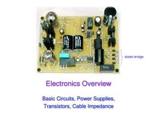
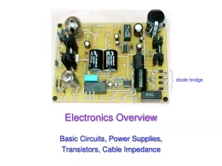
A theoretical background of unregulated power supply is given in this section. As it was mentioned before the waveform will be altered by the filter capacitor which will discharges through RL. The output voltage is given as the following: CHAPTER 1
Since the discharge time of the capacitor is from one peak to approximately the next peak tdis T when VCreaches its minimum value. Since RC >> T, T/RLC become much less than 1 (which is usually the case), Therefore The peak-to-peak ripple voltage is: CHAPTER 1
In the meanwhile, VDC can be found through Vc(min) Ripple factor CHAPTER 1
EXAMPLE Determine the ripple factor for the filtered bridge rectifier with a load as indicated in the following figure CHAPTER 1
THE PROJECT PART 2 CHAPTER 1
DEFINITION OF A PROJECT To put projects into perspective we need a definition a common starting point. Projects actually have a very specific definition. If a set of tasks or work to be done does not meet the strict definition, then it cannot be called a project. To use the project management techniques presented in this chapter, we must first have a project. Our definition of a project is given below. This definition tells us quite a bit about a project. To appreciate just what constitutes a project let us look at each part of the definition. CHAPTER 1
WHAT IS A PROJECT? A project is a sequence of unique, complex, and connected activities having one goal or purpose and that must be completed by a specific time, within budget, and according to specification. CHAPTER 1
SEQUENCE OF ACTIVITIES A project comprises a number of activities that must be completed in some specified order. At this point we simply say that an activity is a defined piece of work. That rather informal definition of an activity will be replaced later with a very precise definition. The sequencing is based on technical or best practice requirements, not on management prerogatives. It is often helpful to think in terms of input and output. The output of one activity or activities becomes the input to another activity or activities. In other words, what is needed in the way of input in order to begin working on this activity and what activities produce those as outputs. Avoid the trap of specifying sequence based on resource constraints or such statements as: Mohamed will work on activity B as soon as he finishes working on activity A. We are not going to ignore resource constraints when we actually schedule activities. That decision will come later in the project planning activities. CHAPTER 1
UNIQUE ACTIVITIES The project has never happened before and will never happen again under the same conditions. Something will always be different each time the activities that comprise this project are repeated. Usually the variations from time to time will be random in nature a part is delayed, someone is sick, a power failure occurs, and so on. These are random events that we know will happen but when, how, and with what impact on the schedule we are not exactly sure. It is these random variations that give rise to the challenge for the project manager. CHAPTER 1
COMPLEX ACTIVITIES The activities that comprise the project are relatively complex. That is, they are not simple, repetitive acts, such as mowing the lawn, running the weekly payroll, washing the car, or loading the delivery truck. Rather they are new, and require special skill levels, creative input, and judgment to be done effectively. CHAPTER 1
CONNECTED ACTIVITIES There is some order to the sequence in which the activities that make up the project must be completed. Connectedness follows from the fact that the output from one activity is input to another. The alternative is a list of tasks that are unconnected but must all be complete in order for the project to be complete. As a simple example, consider painting the interior rooms of a house. Except for rather unusual situations, the rooms can be painted in any order. The house is not completely painted until all its rooms have been painted but they may be painted in any order. Painting the house is a collection of tasks, but it is not a project in the sense that we have defined project. CHAPTER 1
ONE GOAL Projects must have a single goal as compared to a program, which can have many goals. Programs are therefore a collection of projects that may have to be completed in a specific order for the program to be completed. There will be situations where a project may be divided into several subprojects, which are each project in their own right. For better management control this may happen in very large or complex projects. For example, subprojects may be defined at the department, division, or geographic level. The complicating factors may be that the projects are now interdependent. While this adds another layer of complexity and communication, it can be handled. CHAPTER 1
SPECIFIED TIME Projects have a specified completion date. This may be self imposed by management or externally specified (as by a customer). Often the deadline is beyond the control of anyone, such as firing a rocket at a distant comet as it swings near the earth's orbit, or holding a trade conference. In both cases the project is over regardless of whether the project work has been completed. CHAPTER 1
WITHIN BUDGET projects also have resource limits (people, money, and machines). while these may be adjusted up or down by management, they are considered fixed resources by the project manager. CHAPTER 1
ACCORDING TO SPECIFICATION The customer or recipient of the deliverables from the project expects a certain level of functionality and quality from the project. These may be self imposed or customer specified, and are fixed as far as the project manager is concerned. While the project manager treats them as fixed, that is not the reality of the situation. There are any number of factors that will cause the specification to change. For example, the customer may not have defined requirements completely, or the business situation may have changed (as happens in long projects). To expect the specification to remain fixed through the project is unrealistic. In fact, if it did, the job of project manager would be much less exciting and challenging. Systems specifications can and will change. This presents special challenges to the project manager. We will show you how to handle them effectively. CHAPTER 1
WHAT IS A PROGRAM? A program is different from a project. Programs are larger in scope and comprise multiple projects. For example, the United States government has a space program that includes several projects, such as the Challenger Project. Or Construction Company contracts a program to build an industrial technology park with several separate projects. CHAPTER 1
PROJECT PARAMETERS Scope, cost, time, and resources define a system of four constraints that operate on every project. They are an interdependent set in the sense that as one change it may cause us to change the others so that we can restore equilibrium to the system. Because they are so important to the success or failure of the project, we will spend a few minutes discussing them here. CHAPTER 1
COST Throughout the project management life cycle, cost is a major consideration. The first consideration occurs at an early and informal stage in the life of a project. The requesting client may simply offer a cost figure about equal to what they had in mind for the project. Depending on how well thought out it was their number could be fairly close to or far from the mark. Consultants will often encounter situations in which the client is willing to spend only a certain amount for the work: Do what you can with what you have. In more formal situations (the ones we will learn in this course) the project manager will prepare a proposal for the work to be done. That proposal will include a good estimate (perhaps even a quote) of the total cost of the project. Even if a preliminary figure had been given, the client's decision will be based on better estimates of cost and time. The decision is the second milestone. CHAPTER 1
TIME To a certain extent cost and time are trade‑off with one another. The time can be reduced but cost will increase as a result. Time is an interesting resource. It can't be inventoried. It is consumed whether we use it or not. For the project manager, the objective is to use the time allotted to the project in the most effective and productive ways possible. We will learn that time can be a resource to be traded within a project or across projects. Once a project has commenced, the prime resource available to the project manager to keep the project on schedule or get it back on schedule is time. Good project managers realize this and will protect their time resource jealously. We will have more to say about this later when we talk about scheduling project activities CHAPTER 1
RESOURCES While all resources can be discussed in terms of cost, we choose to identify resources separately. We have in mind such resources as equipment, physical facilities, inventory, and others. These are capital assets that have limited availabilities, can be scheduled, or can be leased from an outside party. Some are fixed; others are variable only in the long term. In any case they are central to the scheduling of project activities and the people are the major resource. Another resource for systems projects is the availability of computer processing time (mostly for testing purposes), that can present significant problems to the project manager when it comes to project scheduling. CHAPTER 1