
Program bumper & limit switches in autonomous mode
Program bumper & limit switches in autonomous mode. Program bumper & limit switches in autonomous mode.

Program bumper & limit switches in autonomous mode
E N D
Presentation Transcript
Program bumper & limit switches in autonomous mode Performance Objective: Given the components of a VEX robotics design system program a bumper switch [and limit switch] in autonomous mode to have the robot back up for two seconds after coming in contact with a wall, then terminate the program. Enabling Objectives: define autonomous programming and its purpose explain the difference between inputs and outputs explain the difference between digital and analog sensors describe a variable and its purpose in programming
Program bumper & limit switches in autonomous mode Enabling Objectives: describe the types of conditional expressions used in VEX programming describe the difference between a bumper and limit switch draw a flow chart for using a bumper switch verify a bumper switch program a bumper switch utilize Competition Switch Simulator
Autonomous Programming Autonomous means that you program the robot to do something on its own You do not control the robot with the Joystick in autonomous mode The purpose of autonomous programming is to have a self-controlled robot
Inputs & Outputs (I/O) In autonomous programming you work with inputs and outputs An input in the case of VEX is an input device An input device provides data and control signals to the microcontroller The input devices used with VEX are sensors
Inputs & Outputs (I/O) An output is an electrical signal from the microcontroller used to drive an output device An output is usually observable, such as a motor running Some sensors utilize both inputs and outputs to perform their function
Digital & Analog Inputs and outputs will be either digital or analog Digital I/O are discrete, meaning on or off; true or false; 1 or 0 1 or 0 is used within a programming language to express a digital value Think of a light switch, it is either on or off (true or false, 1 or 0) there is no in between
Digital & Analog Analog I/O are continuous, meaning the value can range from a minimum value to a maximum value, with an infinite number of possibilities in between Think of a light that is connected to a dimmer switch, the light can be off, or it can vary in brightness up to its maximum brightness level
Variables In order to use a sensor, you must first define a variable in the software A variable is a symbolic name given to some known or unknown quantity or value (memory address) In VEX programming the variable name can be only a single string of letters When using a digital sensor, the input value (1 or 0) will be stored in the variable name
Variables The most common variable type that we will use in VEX programming is an integer (int) An int allows you to store the data type value of the sensor in the variable name You can then recall the variable name throughout a program
Conditional Expressions Conditional expressions allow a program to make a decision based on certain information Common examples of conditional expressions are: while loops and if-then-else statements
While loops While loops perform a task while a statement is true or not false Recall from operator mode: while 1 is true, perform tank mode
If-then-else Statements These statements test a condition, if the condition meets the criteria then perform a task, else-if a different condition is met, then perform a different task
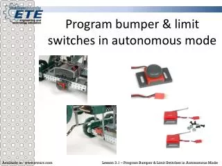
Bumper versus limit switch The two switches perform the same function The main difference between a bumper switch and a limit switch is the mechanism used to receive the signal A bumper switch uses a button A limit switch uses an arm When the button or arm is pressed, the same signal is sent to the microcontroller from the sensors
Programming a bumper switch versus a limit switch This lesson will walk you through the steps to program a bumper switch To program the two switches the same steps are followed The sensors do use different function blocks in easyC
Flow Charting When programming it is helpful to draw a flow chart of a program before you actually write the code The action allows you to see how the program will operate and get a clear picture of how the code should flow When flow charting, there are specific blocks or symbols that are used
Flow Chart Symbols Start Bumper Switch Input No Decision A Yes Decision B End Start and End Symbols Arrows Input/Output Conditional Decision
Flow Charting When flow charting use the symbols to plan out your program Add in the actions you want to perform
Flow Charting Start Bumper Switch Input No Decision A Yes Decision B End This flow chart goes through the following process: Check bumper switch If bumper switch is no, repeat process If bumper switch is B, then end the program
Flow chart a Bumper switch Flow chart a bumper switch and motors on the activity sheet If the button is not pushed, move the robot forward If the button is pushed, stop the robot for 1 second, backup for 2 seconds Show your instructor before continuing
Verifying a Sensor Begin by checking the port which the sensor is plugged into Configure the motors and Sensor(s) in the main program tab Start a New Competition Project After starting a new project you will see five tabs, click on the Operator Control tab
Verifying a Sensor Notice the while loop has already been inserted Insert a driving mode (tank or joystick) function for two motors into the existing while loop Set the motor numbers according to your configuration
Verifying a Sensor Before downloading the code, be sure to prop your robot up so that the wheels are not touching a surface Build and Download the new code Close the Loader window Under Tools, open the On-line Window Enable the On-line Window
On-line Window Enable/Disable Configura-tion set by you Test motors Verify Sensors
Verify Sensor with On-line Window Recall which port the bumper switch is plugged into Look at that port in the digital I/O box Now push the bumper switch Notice the value is 1 when the bumper is not pushed and 0 when pushed
Program a Bumper Switch in Autonomous mode Close the On-line Window Click on the Main tab Double click on the Globals icon Define a new global variable as an integer (int) variable for the bumper switch Name it Click on the Autonomous tab Insert while loop where 1==1
Program a Bumper Switch in Autonomous mode Insert a bumper switch input from the function block tree into the while loop Select the appropriate Digital input port Select the variable where to send (Retrieve to:) the value from the sensor (this is what you named the variable you created) Click ok
Program a Bumper Switch in Autonomous mode Insert an If statement from the Program Flow menu Write the If Statement If bumper(insert your variable name) ==0
Program a Bumper Switch in Autonomous mode Refer to your flow chart to insert the proper functions into the if statement If bumper == 0, it means that the button is pushed You want the robot to stop for 1 second and then backup for 2 seconds, and then stop Use a Wait function to pause for a certain amount of time The wait command counts in milliseconds, remember 1 second = 1000 milliseconds Try to write the above statements into your If statement After you have attempted to write the code, refer to the next slide for the solution
Program a Bumper Switch in Autonomous mode Stops the motors Waits 1 second Reverses motors Waits 2 seconds (allows motors to stay in reverse for two seconds) Stops motors
Program a Bumper Switch in Autonomous mode After the robot runs in reverse, we want the program to terminate (stop running) To do this enter a Return function from the Program Flow menu This Return command sends the robot back to the main code window, where the autonomous program is told to end by default
Program a Bumper Switch in Autonomous mode Refer to your flow chart If the bumper switch is not pushed, we want the robot to continue to moved forward To do this enter an Else Statement below the If statement In this Else statement insert the proper motor modules to move the robot forward
Program a Bumper Switch in Autonomous mode You want the while loop to continue to run through the else statement when the bumper switch is not pushed in order to keep the robot moving forward
Testing Your Autonomous Code Build and Download your code Leave the IFI Loader Window open At the bottom is the Competition Switch Simulator This simulator allows you to test you autonomous code
Testing Your Autonomous Code First click Disable, this stops the program from running Next, click on Autonomous Then click Enable, this will run your autonomous program You can repeat this process to retest you program
Program Terminated Congratulations, your robots program should terminate with the bumper switch Show your success to your instructor If your program is not functioning properly, read through the lesson again to see if you can find the faults, if you still cannot get your robot to operate properly, ask your instructor for assistance