Download
1 / 54
570 likes | 1.03k Views
LDL and other synchronizers for GALS and MCD. 048879 Druyan Barak. Outline. Gals system Stopable Clocking Timed clock trees Matched delay port control Minimize ACK latency LDL synchronizers MCD synchronizers 4 phase synchronizers 2 phase synchronizers. To remind the problem ….

E N D
LDL and other synchronizers for GALS and MCD 048879 Druyan Barak
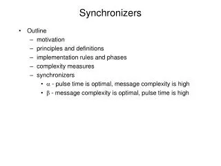
Outline • Gals system • Stopable Clocking • Timed clock trees • Matched delay port control • Minimize ACK latency • LDL synchronizers • MCD synchronizers • 4 phase synchronizers • 2 phase synchronizers
To remind the problem … • Hard to design a single clock distribution network in a large SoC • Skew, other variations, min-delay, max-delay • Large (clocked) chips have multiple clock domains, because: • chip interfaces with several unrelated clocks • chip size grows—more economical to break the chip into “multi-sync” domains • DVFS—different frequencies in different parts and they vary over time • Cross-domain communications require (clock and/or data) synchronization
GALS system at stop-able clocking • The locally synchronous island enables an output (input) GALS port when it wishes to send (receive) data. • The GALS ports from different modules communicate with each other using a simple asynchronous handshake protocol. • The GALS ports can pause the local clock to ensure synchronization between modules if necessary.
Stoppable Clock Generation - Analysis (I) • Stretch Condition: • Size of stretch window : • For long clock cycle the clock will never be stretched. E.g. if each of the constant delays in Eq. (I) were 1 ns, operating at slower than 125MHz will guarantee no clock stretching.
Synchronization failures – the conflict Starting from X+, the conflict occurs when
Synchronization failures – the conflict example • Starting from X+ the conflict occurs when:
Limited Delay Clock Trees S A F E S A F E
Timed Clock Trees - disadvantages The clock tree delays must be verified manually after each layout iteration and clock tree design The solution is not scalable The solution may be sensitive to thermal and power supply voltage changes (different changes in , TSU, TH and DNOR). (R+ D+) is not easy to determine accurately
Long Delay Clock Tree (DCLK > T) • Generalization of the “limited delay clock tree” solution • The port access is allowed only during the Safe intervals • Verify: • Pros and cons are similar to “Limited Delay Clock Tree” solution
Matched Delay Port Control - Disadvantages • In designs with high clock rates and long clock delays, the clock stretch will happen each handshake – “slow” architecture. • In addition, same disadvantages as the “limited delay clock tree” (scalability, sensitivity …)
Optimization – double latching mechanism (widen safe region)
LDL synchronization Locally Delayed Latching does not require stopping the clock of locally synchronous islands. It synchronizes incoming data by means of locally delayed sampling.
LDL circuit An asynchronous input port control both the input latch and Y1, the clock input to the first sampling register. The local clock Y is uninterrupted. Y1+ is delayed when a conflict is imminent. Y1- is unaffected.
Definitions Resolution – a meta stable MUTEX resolves when the value stored in its internal latch is set none deterministically to either 1 or 0. Failure – a circuit is said to fail if a combinational function of the output of meta stable MUTEX of that circuit does not resolve within a predefined maximal time T_ms Safety – a circuit is M safe if the expected time between two failures exceeds M. Min High Clock Phase – T_hp is minimally allowed clock high phase time for a FF (typically about three FO4 inverter gate delays).
LDL constraints • High-Phase should be long enough: • The worst case occurs when the incoming REQ conflicts with clock Y and REQ wins the arbitration, possibly after the metastability resolution time M/S. In this case, the high-phase of Y1 (HP) is maximally shortened. • The shorter cycle leaves less time for computing in the combinational logic immediately following the first register
LDL constraints • To prevent metastability in REG2, we require: • Operating at 200 Mhz with 0.13 um, preserving one quarter of the clock cycle for MUTEX resolution we obtain MTBF of about 3000 years.
Decoupled Input Port – for LDL • The slide shows an implementation of input port for Locally Delayed Latching. • Without a conflict, Y1+ is either not delayed or delayed by less than DCTRL. R2+ is granted only during the low-phase Y. • The MUTEX arbitrates any conflict between R2+ and Y+. • When R2+ wins over Y+, the asynchronous controller is granted (R3+). • The controller employs an asymmetric matched delay DoDi to open the latch and then close it again (L+L–). • After R2–, Y1+ triggers REG1, leading to a shortened cycle in the combinational logic following REG1 (the cycle is shortened by DCTRL). • If the clock wins over R2+, R3+ happens only half a cycle later, after Y–.
Decoupled Input Port - STG • The controller delay is measured along the red dashed path • The path is contained entirely inside the input port of the synchronous island, thus we ensure that the clock cycle reduction depends solely on the input port control logic (and does not depend on the logic and clock of the transmitter module).
Decoupled Output Port • The internal acknowledge (A1) is decoupled from the external asynchronous handshake. • At the beginning, the synchronous island posts the data and initiates the internal request (R1+), which is passed directly to the external interface (R2+). • When the acknowledgement is received (A2+), it is passed to the MUTEX (A3+) and in parallel the external request R2 is released (R2–). • The MUTEX resolves any conflict between A3+ and the local clock Y. • When A4+ wins over Y+, A1 is set. • The design assumes that the controller delay [R1– A1–] is much less than the clock period, which is very realistic
Simpler Input Port – eliminating the asynchronous controller The following architecture simplifies the receiver side, eliminating the asynchronous controller from the input port. The receiver delay Dctrl now depends on the external delays of the transmitter
Controller delays • The three circuits of “Locally Delayed Latching” technique were tested using following design flow: • Synthesized by Petrify • Converted to VHDL • Synthesized by the Synopsis Design Compiler using 0.35m CMOS libraries • Verified by gate level simulations with wire-load model delays (SDF)
Conclusions • Previously proposed locally generated, arbitrated clocks for GALS SoCs face the risk of synchronization failures if clock delays are not accounted for • A few methods to overcome the problem have been presented: • In some cases, it is sufficient to extract all the delays and verify whether the system is susceptible to metastability • In other cases, when high data bandwidth is not required, asynchronous synchronizers or matched-delay asynchronous ports may be employed
DVFS – Dynamic Voltage Frequency Scalling Voltage and Frequency change over time Clock relationships change over time Need universal synchronizers that support varying relationships
Inter-MCD Communication Data transfer between different clock domains should be performed carefully Incoming data change near receiver clock sampling edge causes meta stability, which may lead to a functional failure
In 1 Out 1 Data conflict Long Delay In 2 Out 2 Terrible data conflict In 3 Out 3 Metastability Asynchronous failures Clock tpd tsu+ th
Synchronizer MTBF – Mean Time between Failures • Given meta stability at t = 0, probability of meta stability at t > 0 = e-t/t • Failure: Still meta stable by next clock • Rate(failure)=Rate(enter m.s)p(still m.s. after T) =W Fc Fd e-T/t • MTBF = 1/ Rate( failure) =
Synchronizer MTBF – Mean Time between Failures Meta stability happens so we need to protect our circuits with a meta stability-tolerant design Example: FC=1GHz MHz, FD=100MHz
data BFF RDY enable FF1 FF2 Clock B 2-Flop Family Concepts • We know that metastability happens • We need to protect our circuits with a metastability-tolerant design • How ? • Allow time S for settling Why two FFs? To allow a complete cycle for settling ! Settling time (S): 2 cycles Latency (from RDY+ to data latching): At least 2, up to 3 S
4-Phase Protocol REQ PUSH CHANNEL (DATA & REQ SAME DIRECTION) ACK n DATA DATA REQ ACK
2-Phase Protocol REQ PUSH CHANNEL (DATA & REQ SAME DIRECTION) ACK n DATA DATA REQ ACK
Standard 4-phase synchronizer • One clock cycle is preserved for the meta stability resolution and no logic is allowed (red). • The exact time required for single synchronizer meta stability resolution is derived from MTBF • When the time required for meta stability resolution is longer than one cycle, additional flip-flops can be inserted. • This synchronizer is limited to low data rates – in typical cases 6Tx and 6 Rx cycles are require for a complete and acknowledge transfer of single word
Agresive 4-phase synchronizer • When fast clocks are used either in the transmitter or in the receiver or both a single cycle time may be insufficient for reliable operation.In this case the time for meta stability resolution can be extended by inserting additional FF’s. • The output of the resolving FF is marked in red. These lines require special treatment to allow for sufficient resolution time. They should not be combined with other parts of the logic by the synthesis.
STG and TX FSM The synchronizer waits for data which is indicated by rising VI. The transmitter output registers (REGD and REGV) are enabled and will send out the new data word and REQ. At the receiver side if the receiver is ready (READY is high) DATA is sampled by REGR and VO pulse is generated after R2 rises. Once ACK sampled A2 disables TX output registers and asynchronously reset REQ.
Aggressive 2-phase synchronizer • The synchronization data rate can be significantly improved by employing a two phase protocol. This is particularly important for long range communication where wires incur additional high latency. • ACK generation is symmetric for ACK+ and ACK- (no asynchronous resets) • The time reserved for meta stability resolution is shorter that in 4phase synchronizer by the XOR delay