Download
1 / 73
730 likes | 851 Views
This course simplifies the complicated optical system used in lithographic projection cameras for making computer chips. Students will work with a simple optical system to observe basic principles and learn about the relationship to real lithographic systems through a commercial simulator.

E N D
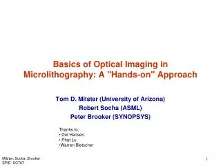
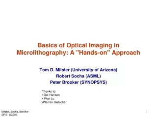
Basics of Optical Imaging in Microlithography: A "Hands-on" Approach Tom D. Milster (University of Arizona) Robert Socha (ASML) Peter Brooker (SYNOPSYS) • Thanks to: • Del Hansen • Phat Lu • Warren Bletscher Milster, Socha, Brooker SPIE- SC707
Grating (Mask) Source Aperture Image Plane (Aerial Image of Mask) Stop CCD Camera (AIMS) Lens 2 Lens 1 Condenser fc f2 f1 2fcam fc f1 f2 2fcam What we want to do with this course • Take a complicated optical system, like a lithographic projection camera used to make computer chips, and simplify it to a working model that demonstrates basic principles. • Use a simple optical system for the student to work with “hands on” and observe the results. • Demonstrate the relationship of the simple system to a real lithographic system through a commercial simulator. • Have fun and demonstrate our unparalled acting abilities From This To This Milster, Socha, Brooker SPIE- SC707
OUTLINE • Intro • Basic Imaging – What we do in lithography • The goal of making a small image • What limits the size of the image? • Basic Illumination and Imaging • Koehler Illumination • Definition of coherence factor “sigma” • Binary Mask • Contrast versus pitch for sigma ~ 0 • Contrast versus pitch for sigma > 0 • 2-Beam and 3-Beam Imaging • Focus behavior • Phase Mask • Contrast versus pitch • Focus behavior • Off-Axis Illumination • Contrast versus pitch • Focus behavior • Summary Milster, Socha, Brooker SPIE- SC707
z y X Introduction • What is photo lithography ? • Optical image is recorded in the resist via changes in concentrations of species. • Concentration level controls development Object: reticle or mask Optics Photoresist Aerial Image Wafer + films Latent Image Photoresist Development Resist Cross sections Negative Photoresist Positive Photoresist • Etymology: Photolithography = Light Stone Writing Milster, Socha, Brooker SPIE- SC707
Introduction • 1st approximation is that Aerial image propagates into photoresist normal to the wafer plane, creating a latent image • Reality is more complicated; you need to calculate E fields in photoresist at many propagation angles 0.25mm 5-BAR Structures Focus=0.0mm, NA=0.57 NA=0.6, 248nm Z Image Cross Section Z Resist Cross Section (not top down!) Milster, Socha, Brooker SPIE- SC707
Introduction • The goal of making a small image • Transfer image into a photosensitive material, i.e., photoresist, for subsequent processing that results in a desired pattern to be used as a “stencil” photoresist Milster, Socha, Brooker SPIE- SC707
Introduction • Imaging Resolution and Lord Rayleigh • Q: When can you resolve the image of 2 distance stars? • A: When the 1st Intensity min of one lines up with peak of other Large l Small NA Decrease l Increase NA Large NA From the math of the Airy function Web Top Optics, 1999 Milster, Socha, Brooker SPIE- SC707
Oh Master-Litho… • ..what limits the size of the photoresist pattern? • Grasshopper, there are three paths to improve resolution: • Reduce Wavelength (Lambda) • Increase numerical aperture (NA) • Decrease k1 : “Process” knob • Includes off-axis illumination, complex masks, high contrast photoresist, acid diffusion, etc… • ….now go away Grasshopper I am busy. Milster, Socha, Brooker SPIE- SC707
What is it now Grasshopper… • Master, what affects the contrast of the image? • The answer is found in the values of • NA • CD and Pitch • Partial Coherence or illumination (s) • s=0: Coherent Limit • s=1: Incoherent Limit Milster, Socha, Brooker SPIE- SC707
You again grasshopper… • Master… • …look at the following data Milster, Socha, Brooker SPIE- SC707
Effect of Varying s • Master, how come in one case increasing sigma is good (100nm L/S) and in the other case, increasing sigma is bad (200nm L/S)? • It depends on the amount of diffraction orders that are being collected by the lens…now go away! l=193nm, NA=0.75 Dense Lines vs. s (circular) 150nm L/S 100nm L/S Milster, Socha, Brooker SPIE- SC707
Master, I am sure that your answers are correct but… • …yes Grasshopper… • But I find these facts confusing. What is sigma? How can in some cases a larger sigma be good and in other cases a larger sigma be bad? And what the heck is k1? • Master…I do not want only the answers…I want to understand…please help me understand master… • Grasshopper… you are finally asking the right question • Go to the optical bench now… • It holds the answer to your questions!! Milster, Socha, Brooker SPIE- SC707
Grating (Mask) Source Aperture Image Plane (Aerial Image of Mask) Stop CCD Camera (AIMS) LED Source Lens 2 Lens 1 Condenser fc f2 f1 2fcam fc f1 f2 2fcam Basics of Imaging in Lithography: Experimental Layout Milster, Socha, Brooker SPIE- SC707
First Light – Get An Image Let’s do an experiment: • Set up the bench with: • Pinhole Source • Aperture Stop of 6.35 mm (1/4 in) diameter. • Put in the L (25.2µm) pitch mask and observe the aerial image. • The grating simulates a mask. • The aerial image simulates what is used to expose the resist. • In our system, the aerial image is reimaged onto a CCD camera, which is like an Aerial Image Measurement System (AIMS). • Draw picture of the light pattern at the stop. Milster, Socha, Brooker SPIE- SC707
Basic Illumination and Imaging • Kohler Illumination Image of source Stop Mask Plane Source Aperture Lens 2 Aerial Image Lens 1 Condenser Imaging Lens • Field Stop of Imaging Lens is Aperture stop condenser and vice versa • Lithographic systems use Koehler illumination where the illumination source aperture is imaged into the stop of the imaging lens. Milster, Socha, Brooker SPIE- SC707
Basic Illumination and Imaging • Definition of Coherence Factor ‘Sigma’ Stop Diameter Source Image Diameter Mask Plane Pupil Edge (the “NA”) Source Source Image Imaging Lens View of Entrance Pupil with blank mask Condenser Milster, Socha, Brooker SPIE- SC707
E +1st -1st 0th Simple Binary Mask • Model a Cr on quartz grating mask as an infinitely thin grating Note: For 1:1 lines and spaces, P= 2 * LW LW = Line Width P SiO2 Cr E-Field Position -3 +3 Grating Equation: q Diffraction Orders -2 +2 -1 +1 0 Lens/Pupil Milster, Socha, Brooker SPIE- SC707
Effect of Varying Pitch • Let’s do an experiment • Set up the bench with: • Pinhole Source • Aperture Stop of 6.35 mm (1/4 in) diameter. • Use the S(8.4µm), M(12.6µm) and L(25.2µm) pitches of the mask and observe the effects in the image plane and at the stop. • Draw the light pattern at the stop on the next page. • What is the relationship between the light pattern at the stop and the image? • What is the smallest pitch for which we can obtain an image? • This system is very similar to what would be observed if an on-axis laser beam was used to illuminate the mask. Therefore, we call this case coherent imaging. • Notice that the lines in the image are either completely resolved, or they are not. There is no ‘partially resolved’ case. Milster, Socha, Brooker SPIE- SC707
Effect of Varying Pitch Milster, Socha, Brooker SPIE- SC707
Binary Mask and Diffraction Orders • Must have more than 1 order in pupil to have image modulation +3 Pupil (stop) +1 Strong Image Modulation o -1 We see diffraction orders emanating from the mask that are necessary for imaging. -3 For 1:1 grating Coherent limit pupil +1 qMax o Pminis the minimum pitch that is at the limit of resolution. -1 NA=sin(qMax) k1=1/2 +1 pupil qMax No Image just constant Irradiance o -1 Milster, Socha, Brooker SPIE- SC707
Coffee Break Milster, Socha, Brooker SPIE- SC707
Time for the Late Shows new and exciting quiz game sensation. • Do you want to play: • Know your “Current events”? • Know your “Cuts of Beef’? • Know your “Optics Bench Basics”? • Know your Bench Basics! Excellent choice!!! Milster, Socha, Brooker SPIE- SC707
Grating (Mask) Source Aperture Image Plane (Aerial Image of Mask) Stop CCD Camera (AIMS) Lens 2 Lens 1 Condenser fc f2 f1 2fcam fc f1 f2 2fcam Bench basics: • Where is the Source Aperture relative to the condenser lens? • Is it: • A: at minus infinity • B: it refuses to reveal its location • C: The source aperture is located at the front focus of the condenser lens • Answer is C: The source aperture (effective source for the system) is located at the focus of the condenser lens. Collimated light from the LED illuminates the grating. Light from every part of the source aperture illuminates each point on the grating. Milster, Socha, Brooker SPIE- SC707
Grating (Mask) Source Aperture Image Plane (Aerial Image of Mask) Stop CCD Camera (AIMS) Lens 2 Lens 1 Condenser Bench basics • Q: Where does the image of the Source Aperture appear? • Does it appear … • A: only in the Borg space time continuum • B: at the grating • C: in the plane of the “Stop”. • Correct answer is C: The image of the Source Aperture appears in the plane of the stop. fc f2 f1 2fcam fc f1 f2 2fcam Milster, Socha, Brooker SPIE- SC707
Grating (Mask) Source Aperture Image Plane (Aerial Image of Mask) Stop CCD Camera (AIMS) Lens 2 Lens 1 Condenser fc f2 f1 2fcam fc f1 f2 2fcam Bench basics • Q: Collimated light from the Source Aperture illuminates the Grating. This is because…. • A: The grating is not worthy of the sources “focused” attention • B: The source is the grating…question is irrelevant • C: Kohler Illumination of the grating averages out non uniformities in the source. • Answer is C Milster, Socha, Brooker SPIE- SC707
Comedy writer’s strike… • No more multiple choice answers • Let’s continue to cement the concepts associated with the bench Milster, Socha, Brooker SPIE- SC707
Grating (Mask) Source Aperture Image Plane (Aerial Image of Mask) Stop CCD Camera (AIMS) Lens 2 Lens 1 Condenser fc f2 f1 2fcam fc f1 f2 2fcam Bench Basics • Q: Where is the grating located with respect to Lens1? • A: The grating is located at the focus of lens 1. • Q: Where does the image of the grating appear? • A: The image of the grating appears at the “Image plane” Milster, Socha, Brooker SPIE- SC707
Grating (Mask) Source Aperture Image Plane (Aerial Image of Mask) Stop CCD Camera (AIMS) Lens 2 Lens 1 Condenser fc f2 f1 2fcam fc f1 f2 2fcam Bench Basics: • Q: If the Image occurs at the image plane, why is the microscope needed? • A: The image of the source at the image plane cannot be seen with the eye. The microscope is needed to magnify the image so it can be seen by your eye. Milster, Socha, Brooker SPIE- SC707
Grating (Mask) Image Plane (Aerial Image of Mask) Stop Lens 2 Lens 1 f1 f2 f1 f2 Bench Basics: Grating off axis point • Q: Look at the above picture. Estimate the vertical magnification? • ~3.7 • How can the vertical magnification be decreased? • Decrease f2 but keep “Stop” at focus of Lens2. Milster, Socha, Brooker SPIE- SC707
Connection back to real Scanner Optics • Q: Where is the mask plane and image of the mask? • A: First plane on the left and last plane on right. • Q: Can you find the stop in the lens column? • A: On the right side of center. • Q: What is the magnification? • A: 4x demagnification. Milster, Socha, Brooker SPIE- SC707
Effect of Varying Sigma • Let’s do an experiment • Set up the bench with: • Pinhole Source • Aperture Stop of 6.35 mm diameter. • S(8.4µm) grating • Use the PH, 3.18mm (1/8 in) and 6.35mm (1/4in) diameter sources and observe the effect at the stop and at the image plane. Estimate for each source. • Draw the light pattern at the stop on the next page. • Is there a point where we can resolve the lines in the image? • By changing , we are allowing more light through the stop that can interfere to form an image. • Not all of the light that is passed through the stop can interfere, thus giving us background light that reduces our contrast. The amount of background light is a function of the pitch, therefore the contrast is a function of the pitch. • This case is called partially coherent imaging, because of the dependence of the contrast on pitch. Milster, Socha, Brooker SPIE- SC707
Effect of Varying Sigma Milster, Socha, Brooker SPIE- SC707
Contrast Curves versus Pitch & Sigma • Sigma=0.05 ---Coherent • Sigma=0.5 -----Partially Coherent • Sigma=1 ---Incoherent limit Milster, Socha, Brooker SPIE- SC707
Modulation Transfer Function (MTF) • Optics types love this plot!!!! • Can you find the Coherent frequency cut off? Milster, Socha, Brooker SPIE- SC707
No imaging Binary Mask: Influence of Sigma • Pupil diagrams with Partial Coherence : We must have at least 2 conjugate sources points in the pupil to form an image. NA’ σ Imaging!! • Each source point is projected by the diffraction orders from the mask • These will interfere with each other for a given source point • need more than 1 for interference and hence image modulation Milster, Socha, Brooker SPIE- SC707
0th order +1st -1st 0th order Binary Mask: Sigma < 1 Resolution limit with 0<s<1 for a circular source • No grating - just blank mask • Grating period at cut-off frequency • Grating period resolution limit at given +1st -1st 0th order Milster, Socha, Brooker SPIE- SC707
0th order -1st +1st +1st -1st 0th order Binary Mask: Sigma = 1 Resolution limit with s=1 for a circular source • No grating - just blank mask • Grating period at cut-off frequency • Grating period corresponds to incoherent cut-off Milster, Socha, Brooker SPIE- SC707
Binary Mask, l=248nm, NA=0.63 Milster, Socha, Brooker SPIE- SC707
s=0.05 & s = 0.7 for k1=0.5 Milster, Socha, Brooker SPIE- SC707
Different cases for on axis, k1=0.5 • Assume circular, on axis illumination • Assume dense L/S • k1=0.5 • Center of n=1 diffraction orders are at edge of lens • CD = LW = 0.5*Lambda/NA • For 248nm illumination, NA=0.63 • CD = 0.5*248nm/0.63 = 197nm 200nm L/S give k1=0.5 • For 193nm illumination, NA=0.93 • CD = 0.5*193nm/0.93 = 104nm 104nm L/S give k1=0.5 • For 193nm illumination, NA = 1.2 • CD = 0.5*193/1.2 = 80.4nm 80nm L/S gives k1 = 0.5 • Results above are only good for on axis illumination. • The usual off-axis case is different. Milster, Socha, Brooker SPIE- SC707
Binary Mask: Round and Annular Illumination Small s and k1>0.5 Larger s and k1<0.5 • All power is inside pupil (for 0th and 1st orders) • Coherent source points have 3-beam interaction • Some power is inside pupil (center of 1st orders is outside) • Coherent source points have 2-beam interaction Conventional or Circular Source Annular Source Milster, Socha, Brooker SPIE- SC707
Binary Mask: 3-Beam Imaging • Let’s do an experiment • Set up the bench with: • L(25µm) Pitch grating • PH Source • Observe the behavior (position and contrast) of the image as the observation plane is moved from the perfect focus. Write down your observations. • What happens as the observation plane is moved beyond the point of zero contrast? Milster, Socha, Brooker SPIE- SC707
Binary Mask: 3-Beam Imaging • Do you see reversed-contrast lines? • This type of focus behavior is indicative of three-beam imaging, where all of the power from the 0 and +/- 1st diffraction orders passes the stop. • Every point in the image is derived from three conjugate source points in the pupil. • Three-beam imaging has the characteristic that reversed-contrast planes can occur if the focus is too far or the resist is too thick. Milster, Socha, Brooker SPIE- SC707
Binary Mask, l=248nm, NA=0.63, 300nm L/S 3-Beam Imaging Milster, Socha, Brooker SPIE- SC707
Missing Orders • Let’s do an experiment • Set the bench with • L(25 µm) pitch • PH source • Draw a sketch of the image on the next page. • Block the zero diffraction order at the stop. • Draw a sketch of the image on the next page. • Does the pitch of the image change? • This type of focus behavior is indicative of two-beam imaging. • Every point in the image is derived from two conjugate source points in the pupil, which are widely separated and lead to a double-frequency image. • Now change the system to block either the +1 or -1 order, but let the zero order pass the stop. • Draw a sketch of the image on the next page. • Observe the image pitch and defocus behavior. Write down your observations. Milster, Socha, Brooker SPIE- SC707
Missing Orders Milster, Socha, Brooker SPIE- SC707
Binary Mask, l=248nm, NA=0.63, 250nm L/S Milster, Socha, Brooker SPIE- SC707
Etched depth Cr SiO2 d +1 -1 Position Phase Mask P E E-Field -5 Diffraction Orders Grating Equation: +5 -3 +3 q +1 -1 Lens/Pupil +1st -1st Milster, Socha, Brooker SPIE- SC707
Etched depth SiO2 d Pure Phase – Chromeless E +1 P E-Field -1 Position -5 Diffraction Orders Grating Equation: +5 -3 +3 q +1 -1 Lens/Pupil +1st -1st Milster, Socha, Brooker SPIE- SC707
Phase Mask • The phase mask produces no zero order +3 Pupil (stop) +1 Strong Image Modulation -1 No zero order is emitted from the phase mask. -3 For alternating phase shift grating Coherent limit pupil +1 qMax pminis the minimum Cr pitch that is at the limit of resolution. -1 NA=sin(qMax) k1=1/4 +1 pupil qMax No Image just constant Irradiance -1 Milster, Socha, Brooker SPIE- SC707