Download
1 / 41
410 likes | 493 Views
Intense Slow Positron Source. Introduction Science & Frontier Technology Production of e + Competition Proposal Request to EPAC. Introduction. Our motivation: detect deviation from gravity in P s or Hbar free-fall make a beam of anti-atoms ( ≠CERN expts.)

E N D
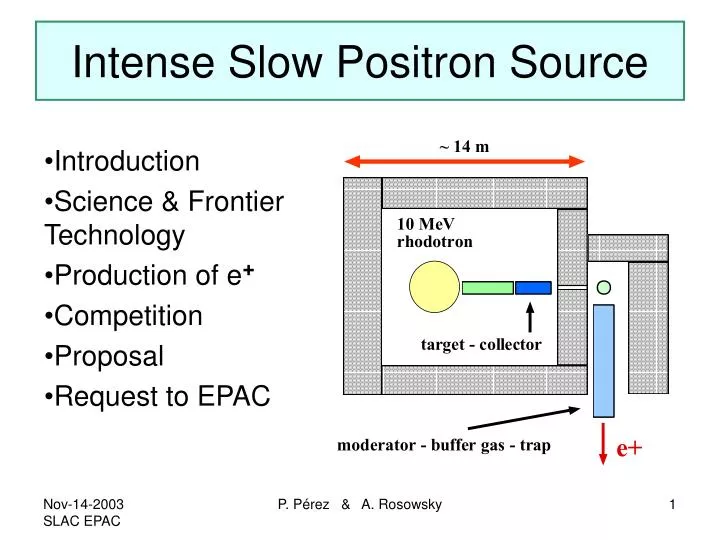
Intense Slow Positron Source • Introduction • Science & Frontier Technology • Production of e+ • Competition • Proposal • Request to EPAC P. Pérez & A. Rosowsky
Introduction • Our motivation: detect deviation from gravity in Ps or Hbar free-fall • make a beam of anti-atoms (≠CERN expts.) • use few pbar (expensive) • use many e+ EC ~ eV , EC ~ 1.5 meV • e+ factory : today’s proposal • New applications outside this field for Ne+ > 109 s-1 P. Pérez & A. Rosowsky
Making anti atoms • Radiative Recombination (RR) ne ≤ 10 8 cm–3 p ++ e– Hp–+ e + Hbar • Laser Induced Radiative Recombination (LIRR) p ++ e– + h H + 2hp–+ e+ + h Hbar + 2h • 3 Body reactions (3BDY) ne ≥ 10 9 cm–3 p++ e– + e±H* + e± p–+ e+ + e±Hbar* + e± e + + e– + e ± Ps * + e ± • Charge exchange with Positronium (CXPS) p ++ Ps H + e +p–+ Ps Hbar + e– H+ Ps H– + e +Hbar+ Ps Hbar+ + e– Matter Anti-matter CERN SLAC P. Pérez & A. Rosowsky
p+ + Ps H + e+ C.M. 20 KeV p– (lab) 10–15 cm2 N.Yamanaka & Y. Kino, Phys. Rev. A 65, 062709 P.K. Biswas,J.Phys. B: At. Mol. Opt. Phys. 34 (2001) 4831 H + Ps H − + e+ 1014Ps at/cm3 10– 4 Hbar + per incident antiproton 20 KeV p (lab) 10−17 cm2 P. Pérez & A. Rosowsky
ATHENA 2.5 108 cm-3 e+ lifetime in plasma (s) Plasma temperature we will be here ! 1012 1014 • Transform all e+ into Ps in less than 1 ns via 3 body reaction: • e + + e – + e ± Ps* + e ± 20 KeV p ± + Ps target H/p = Hbar/p– = 0.1 In same Ps target H+ Ps H– + e+ Hbar+ Ps Hbar++ e– H–/H = Hbar+/Hbar=10-3 1 ns 0.1 ns 1014Ps at/cm3 10– 4 Hbar + per incident antiproton plasma density (cm-3) P. Pérez & A. Rosowsky
Layout scheme Target : aerogel / Si cristal Greaves-Surko traps e+ trap ( ~ eV ) L = 1 cm S = 1 mm2 = 1200 m p+ or p– trap ( ~20 keV ) H, H – or Hbar, Hbar+ Free fall expt. Positronium target : Few 1012 e ± inside 10-2 cm3 => Ps density ~ 1014 cm-3 e–trap ( ~ eV ) several minutes to fill e+trap P. Pérez & A. Rosowsky
(7K) Greaves-Surko trap UC San Diego Ne moderator: Ec < 1 MeV eV N2 buffer gas : eV meV Penning Malmberg trap Rotating wall ATHENA : 108 e+ Project to store 1015 within 3 years1012 1013e+ P. Pérez & A. Rosowsky
Gravity experiment possible with Ps only High Rydberg states of Ps can live ~ 1ms produce thermal Ps atoms (3 km/s max speed) then excited with Doppler-free two photon techniques Ps atoms focused by mirror and converge on 1 m spot deflection expected from gravity is 50 m on a 10 m scale rate of slow positrons needed in order to achieve a 5 measurement in a week of run is ~ 109 s-1 BEC Ps 511 KeV ray laser 3D imaging of molecules Fundamental Physics expts A. P. Mills & P.M. Platzman publications P. Pérez & A. Rosowsky
Other research & Applications • e+ e– plasmas Astrophysics • Feed stellarator for low energy neutral plasma study • Relativistic plasmas study on ms to s time scales • Cold & bright e+ beams materials study • High speed electronics and chips (PALS) • Positron microscopy • Filling of portable trap with 1012 e+ commercial use (UCSD design) • « advanced futuristic » projects : energy storage, USAF shuttle propulsion… P. Pérez & A. Rosowsky
e+ Production and Collection • Beam energy/intensity : 10 MeV 2~10 mA • Target geometry : thin foil at grazing incidence ( 3 degrees) • Probability of first interaction (e+ & Xrays) • Thermal effects : Xrays leak + IR slab effect • Large angle collection and selection < 1 MeV P. Pérez & A. Rosowsky
Target (2) Study energy deposit as a function of incidence angle Thickness = D equivalent thickness: D’ = D / sin 30 D 30 D’ P. Pérez & A. Rosowsky
Kinetic energy at target exit electrons positrons Energy (GeV) Energy (GeV) P. Pérez & A. Rosowsky
Production point At target exit Kinetic energy (GeV) Kinetic energy (GeV) Energy versus angle angle P. Pérez & A. Rosowsky
Magnetic Bulb B target e+ e+ x B B e- dump target e+ P. Pérez & A. Rosowsky
Collection Setup count e+ here 20 cm 50 cm 40 cm 1 m P. Pérez & A. Rosowsky
Simulation and engineering 10 cm P. Pérez & A. Rosowsky
Positrons P. Pérez & A. Rosowsky
electrons P. Pérez & A. Rosowsky
3D view P. Pérez & A. Rosowsky
X = 3 cm X = 200 cm e+ position in (y , z) planes Before 4-poles P. Pérez & A. Rosowsky
positrons electrons Energy (GeV) Energy (GeV) energy versus radius at x = 200 cm Radius (cm) P. Pérez & A. Rosowsky
Kinetic energy < 1 MeV All kinetic energies Radius (cm) Radius (cm) Positrons radius at x = 200 cm P. Pérez & A. Rosowsky
Target e- soldering test on Tungsten 50 m 40 kV / 20 mA on 20 mm2 not perforated at 15 mA Working hypothesis: 1 k W / cm2 3100 K Test with high intensity beam from IBA foreseen T rise, evaporation… P. Pérez & A. Rosowsky
Target (2) Study energy deposit as a function of incidence angle Thickness = D equivalent thickness: D’ = D / sin 30 D 30 D’ P. Pérez & A. Rosowsky
Target (3) e- track length inside targets of 1mm equivalent thickness 30 900 ( cm) ( cm) P. Pérez & A. Rosowsky
Energy Deposit in 1cm2 Target E(e-) = 10 MeV Simulation with GEANT/EGS Deposited power for 1 mA IMAX for 1 kW deposited Power (W) Current (mA) 900 4.5 kW/mA 0.59 mA 30 30 0.22 mA 1.7 kW/mA 900 D’(m) D’(m) P. Pérez & A. Rosowsky
Production Rate (1) 107 electrons on 1 cm2 target e+ forward Ee+<1 MeV Ne+ Ne+ 30 30 900 900 ~ 15000 / 107 = 1.5 10-3 ~ 3500 / 107 = 3.5 10-4 D’(m) D’(m) P. Pérez & A. Rosowsky
Production Rate (2) Power deposited in 1 cm2 target = 1 kW X 109 X 109 e+ forward Ee+<1 MeV Ne+ (s-1) Ne+ (s-1) 30 30 1.4 1012 0.6 1012 900 900 D’(m) D’(m) P. Pérez & A. Rosowsky
Production For 1 cm2 of target D’ = 1mm Limit 1 kW / cm2 Normalization to same number of e- generated 900 in units of 1012 s-1 30 1 2 3 4 5 0.58 mA 2.3 mA for 4 cm2 Ee+ (MeV) P. Pérez & A. Rosowsky
Collection efficiency Fraction of e+ at exit plane inside circle of radius 5 or 2 cm centered on axis r = 5 cm r = 2 cm E < 600 KeV with quad slit shaped beam 5 2 E < 1 MeV 1 x 4 cm no quad 2 x 2 cm transverse radius of e+ source at target level (cm) P. Pérez & A. Rosowsky
Collected Positron Rates(2m from target) (e+ rates in units of 1012 s-1) e+ produced as much as possible near axis is best for production and collection all e+ at exit plane R < 5 cm R < 2 cm E (MeV) P. Pérez & A. Rosowsky
Electron and photon fluxes Two possible setups with same e+ output • Beam and coils on same axis • Target and downstream coils on same axis e- e- P. Pérez & A. Rosowsky
Fluxes of electrons and photons at exit plane I = 2.3 mA Power (kW) Power (kW) Setup 1 Setup 2 plots for 1 mA X (along coils axis) (cm) X (along coils axis) (cm) P. Pérez & A. Rosowsky
A very first design of a 2D expander/uniformizer F. Meot and T. Daniel, NIM, A 379 (1996) 196-205. (m) Z (m) Y (m) x (m) P. Pérez & A. Rosowsky
EPOS design + trap Proposed design MeV e+ converter W moderator e- MeV e+ dump converter e- 1.5 eV e+ extraction lenses Ne moderator E (2-5 kV) trap trap E(decel.) Design differences (1) Rossendorf / Aarhus 1.5 eV e+ P. Pérez & A. Rosowsky
Design differences (2) Proposed design: 10 MeV, 2.5 mA, CW Ne Moderator, thin W target Collection efficiency before trap 20% Expected rate before trap 1.1 1010s-1 Original EPOS design: 40 MeV, 0.25 mA, ~CW Linac Pt or W moderator, 3.5 mm Pt target Neutron activation Collection efficiency before trap 20% Expected Rate before trap 1.6 108s-1 At 10 MeV, 2.5 mA 1mm target = 0.8 108s-1 P. Pérez & A. Rosowsky
Other designs Thermal neutron capture: 113Cd(n,)114Cd = 26000 barn !! By nuclear research reactor FRM2 in Munich (Germany) can reach 1010s-1 Building size: 40 m x 40 m x 30 m P. Pérez & A. Rosowsky
Scientific Goals • Gravity and spectroscopy with Ps H Hbar • Astrophysics “in vitro” • 3D molecule imaging • Ps BEC and 511 KeV Laser • Applied technology : positron microscope P. Pérez & A. Rosowsky
Proposal: best ingredients .. • e+ facility : Ne+ > 109 s-1 • fundamental interaction physics : HEP lab • e– beam expertise and beam research • SR radiation control infrastructure • Interdisciplinary lab • Location near trap development ……….SLAC ? P. Pérez & A. Rosowsky
Ressource Impacts • Building : • new ~ 2.5 M$ • refurbished ~ x00 k$ • Target-collection • Injection ~ 400 k$ • e- machine : • Rhodotron ~ 2.5 M$ • Linac ~ 300 k$ • Parallel project UC San Diego • Moderator • Buffer gas • trap ~ 500 k$ • Infrastructure : • 250 kW • Water cooling • Radiation control, safety … P. Pérez & A. Rosowsky
Requests • Winter workshop: • Start interdisciplinary community • Start SLAC - Saclay project collaboration • Trigger other institutes interest • EPAC feed back: • encourage TDR for june 2004 EPAC P. Pérez & A. Rosowsky