Download
1 / 18
190 likes | 309 Views
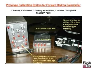
Under HEAVY CONSTRUCTION. LED calibration systems for CALICE hadron calorimeter. Jiri Kvasnicka (kvas@fzu.cz) Institute of Physics, Prague. Outline. Calice prototype SiPM Motivation ( SiPM issues, temeperature drift..) AHCAL 1m^2 solution Electronics solution performance

E N D
Under HEAVY CONSTRUCTION LED calibration systems for CALICE hadron calorimeter Jiri Kvasnicka (kvas@fzu.cz) Institute of Physics, Prague TIPP 2011, Chicago
Outline • Calice prototype • SiPM Motivation (SiPM issues, temeperature drift..) • AHCAL 1m^2 solution • Electronics solution • performance • Embeded solution • Electronics solution • Performance • Quasi-resonant LED driver • Electronics solution • Performance • Light distribution TIPP 2011, Chicago
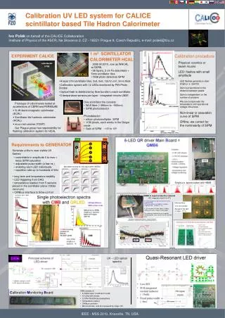
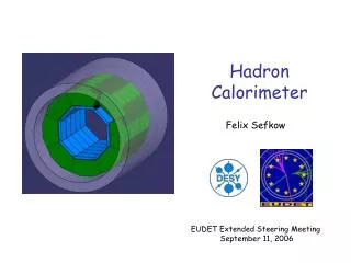
AHCAL 1m2Physics prototype • The AHCAL 1m2 - CALICE experiment • built in 2005 • Testbems 2006-2010 at CERN and FNAL. • Now in CERN as WHCAL • Tested together with ECAL (electromagnetic calorimeter) and TCMT (Muon calorimeter) • 38 layers, 2cm Fe absorbers • 7608 photo detectors (SiPM) in total • One layer • 216 scintillator tiles, 3x3, 6x6, 12 x 12 cm2, • Calibrating system (CMB) with 12 LEDs monitored by PIN-Photo Diodes • Optical flash is distributed by fibre bundle individually to each scintillator • 5 temperature sensors per layer - integrated circuits LM35 • Scintillating tile • 5mm thick Scintillator • WLS (wavelength shifting fiber), ~380nm~500nm) • SiPMphotodetector attached to the WLS fiber + mirror • SiPM(silicone photomultiplier) • 1156 pixels, each works in Geiger mode • Gain of SiPM ~105to 106 TCMT AHCAL` HCAL TIPP 2011, Chicago 20mmFe platesand scintillators ECAL 90 cm 3 cm 1 mm
Calibration Chain: ADC to MIP • AHCAL signal chain: ParticleMIPsScintillatingtilephotons (UV)Wavelength-shifting fibre photons (green)SiPMPhoto-electronsASIC readout • Calibration task: Convert the detector signal to a number of MIP deposited by the particle • The means on calibration: • LED light! • Charge injection • Beam: Muon tracks identification and calibration • Cosmic muons • Other means: Laser, Radioactive material • Measured parameters: • SiPM gain (from Single Photon Spectrum) • Temperature (gain factor -2% per 1K) • Saturation function TIPP 2011, Chicago
TIPP 2011, Chicago Particle detection MUONS LED light
CMB-ToDo • El. Zapojeni, simulace TIPP 2011, Chicago
CMB-results ToDo • Jara’s calibration plots, SPS, etc. TIPP 2011, Chicago
Integrated LED system LEDs • Developed by DESY and Uni Wuppertal • Each Tile has its through-hole mounted LED • Each LED has its own driver circuitry. • Operation: The current pulse though the LED is generated by discharging of the Capacitor by a fast transistor • V-calib signal range: 3–10 V • System tuned for ~8 ns pulses • Choice of the LED is critical for this driver • Several different LED types were tested (see next slide) • The technology of the LED is most important • Only Single-quantum-well LEDs work well (usually UV-LED) • Usual (multi-quantum-well) LEDs have too big capacitance and produce longer optical pulse. On the other hand, they are very bright • Driver circuitry is now optimized and being manufactured on the new HBU for the technological prototype 5 ns TIPP 2011, Chicago
Integrated LED system – Optimization • Pulse of the Blue LED is much wider (~40 ns), than the UV LED (~5 ns) • Light pulse width re-measured with a differential driver • In this mode: LED is reverse biased, then for a short pulse forward biased and directly reverse biased again • The reverse voltage helps to discharge the LED • Blue LED stops shining much faster in differential mode Blue LED Blue LED, differential UV LED TIPP 2011, Chicago
Integrated LED system – SPS • For longer (>30 ns) pulses, both UV and Blue LEDs produce equal optical pulses • Observation: UV LED have much steeper rise time • Driver circuitry is now optimized and being manufactured on the new HBU for the technological prototype • Question: is short pulse necessary? • Answer: Yes, only 15 ns pulses and faster produce decent Single Photon Spectra • Single Photon Spectrum (SPS) • Short pulse -> improvement of the quality • Nice spectrum with UV-LED • Spectrum is more smeared with 30 ns blue-LED Blue LED, 30 ns UV LED, 7ns Blue LED, 15ns TIPP 2011, Chicago
Integrated LED system – Light Yield • Measurements with key components variation • Circuitry was finally tuned to deliver up to 17Keffective pixels • Light referenced to PMT signal • Time behavior of the LED • Measured with PMT • Without tile: sharp pulse • With tile (and Wavelength shifting fibre) long tail 25 ns With Tile Resistorvariation Capacitorvariation TIPP 2011, Chicago
QMB6-ToDo TIPP 2011, Chicago
QMB6-ToDo TIPP 2011, Chicago
Notched Fibre • 24-notched fibre at the left figure. Illuminated by a green laser • Light is emitted from the notches • The notchis a special scratch to the fibre, which reflects the light to the opposite direction • The size of the notch varies from the beginning to the end of the fibre Emission from the fibre (side view) First notch Middle notch End position notch TIPP 2011, Chicago
Optical fibre • Measurements of the light yield • Through the 3mm hole on the PCB (FR4 with filled inner layer) • 3 positions of the notch according to the PCB thru-hole “start” position “middle” position “end” position TIPP 2011, Chicago
Notched fibers configuration • 72 zarezovavlakna – vysledky linearity • LED vyzarovaciprofil (smolda) • Konfigurace 3*24 zarezu HBU1 HBU2 HBU3 HBU4 HBU5 HBU6 TIPP 2011, Chicago
Development of new Quasi-resonant driver (QMB1) • QMB1 (1-chanel LED driver): • Fixed • Topology • Communicating bus (CAN) • CPU (Atmel AVR) • Trigger distribution (LVDS) • Trigger delay can be tuned by C trimmer (~10ns) • Free to adjust: will be discussed at DESY in July calib meeting • Mounting holes (fixation to support/HBU • Fibre(LED) position • Set of notched fibers, semi-automat machine under development • Set: 3*fiber with 24 notches, creating a line of 72 notches. • 3 sets will be delivered HBU1 HBU2 HBU3 HBU4 HBU5 HBU6 TIPP 2011, Chicago
Conclusion TIPP 2011, Chicago