Download
1 / 8
80 likes | 139 Views
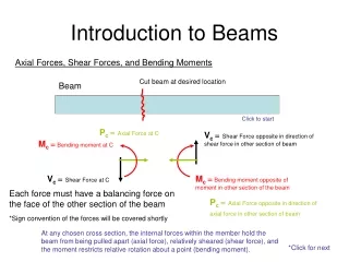
Cut beam at desired location. P c = Axial Force at C. V c = Shear Force opposite in direction of shear force in other section of beam. M c = Bending moment at C. V c = Shear Force at C. M c = Bending moment opposite of moment in other section of the beam.

E N D
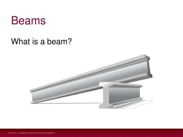
Cut beam at desired location Pc = Axial Force at C Vc = Shear Force opposite in direction of shear force in other section of beam Mc =Bending moment at C Vc = Shear Force at C Mc =Bending moment opposite of moment in other section of the beam Pc = Axial Force opposite in direction of axial force in other section of beam At any chosen cross section, the internal forces within the member hold the beam from being pulled apart (axial force), relatively sheared (shear force), and the moment restricts relative rotation about a point (bending moment). *Click for next Introduction to Beams Axial Forces, Shear Forces, and Bending Moments Beam Click to start Each force must have a balancing force on the face of the other section of the beam *Sign convention of the forces will be covered shortly
Cut beam at desired location Cut beam at desired location y y M M V V x x Positive shear forces have a tendency to rotate the remaining section of the beam in a clockwise direction (Negative Forces rotate counterclockwise). Sign Convention Positive Shear Forces Positive Bending Moments Positive bending moments tend to rotate the beam upwards (Negative Moments rotate downward). *Click for next
3 Basic Steps Determining the internal forces at a particular cross section of a beam typically involves three basic steps. The internal forces consist of the axial force, shear force, and moment acting within the member. 1. Determine the external forces and moments Draw the FBD of the Beam and solve equilibrium equations to find the reactions at the supports. If the beam is part of a structure, reaction forces at supports will need to found for the structure. 2. Cut the beam at the point where the internal forces will be analyzed. Cut the beam at the point which you wish to determine the internal forces (axial force, shear force, and bending moment within the member) and choose one of the sections to analyze. Choose the part with the simplest FBD. If the cut divides a distributed load, don’t represent the distributed load with an equivalent force until after the FBD is obtained. 3. Apply the equilibrium equations to solve for the desired internal forces Use the equilibrium equations to determine the axial force, shear force, and bending moment within the member. Use the correct sign convention for positive shear force and bending moment. *Click for next
Draw the FBD of this beam .25L .75L y x *Beam isolated from surroundings (a) F By using the equilibrium equations, we find that: RAx = Reaction force ON beam at A in x direction X RAx = 0 Point c RAx RAy = .25*F RBy=Reaction force ON beam at B in y direction RBy RAy=Reaction force ON beam at A in y direction RAy RBy = .75*F *Click for next Example Finding Internal Forces F *Figure not drawn to scale Step 1 1. Determine the external forces and moments Draw the FBD of the Beam and solve equilibrium equations to find the reactions and the supports. If the beam is part of a structure, reaction forces at supports will need to found for the structure. A Point C B .25L Step 1 FBD of Beam
.25L y x F RAx = Reaction force ON beam at A in x direction RAx RAy = .25(F) RBy=Reaction force ON beam at B in y direction RBy RAy=Reaction force ON beam at A in y direction RAy *Click for next Example Finding Internal Forces Step 1 Continued Now use the equilibrium equations to solve for the unknown reaction forces. X Point c .25L .75L *Click for next Equilibrium Equations Substituting back into ΣF(i)y equation, we can find RAy: ΣF(i)x = RAx = 0 ΣF(i)y =RAy + .75(F) - F = 0 ΣF(i)y =RAy + RBy - F = 0 ΣM(i)a = 0 = -(.75)*(L)*(F) + (L)*(RBy) RBy = .75(F)
.25L Mc =Bending moment at C Point C Pc = Axial Force at C Vc = Shear Force at C RAy RAy = Reaction force ON Beam at A in y direction y x A free body diagram of the section of the beam that is not used can be drawn later to check the solution. *Click for next Example Finding Internal Forces Step 2 *Section of Beam cut at Point C 2. Cut the beam at the point where the internal forces will be analyzed. Cut the beam at the point which you wish to determine the internal forces (axial force, shear force, and bending moment within the member) and choose one of the sections to analyze. Choose the part with the simplest FBD. If the cut divides a distributed load, don’t represent the distributed load with an equivalent force until after the FBD is obtained.
.25L Mc Apply F = 200 N Given information: Use L = 10 m Pc Vc RAy Example Finding Internal Forces Step 3 *Section of Beam (c) 3. Apply the equilibrium equations to solve for the desired internal forces Use the equilibrium equations to determine the axial force, shear force, and bending moment within the member. Use the correct sign convention for positive shear force and bending moment. By using the equilibrium equations, we found that: *The FBD is known from previous work RAx = 0 RAy = .25*F RBy = .75*F Use equilibrium equations to solve: ΣFx =Pc = 0 From the equilibrium equations we can solve for the axial force, shear force and bending moment. ΣFy = RAy– Vc = 0 Vc= (.25*200N) Vc= 50 N Mc= 125 Nm Pc = 0 ΣM(i)c = Mc – (.25)*(L)(RAy)= 0 Mc= (.25)*(10m)*(.25*200N) *Click for next
Apply F = 200 N Mc Use L = 10 m Pc .75L Vc RBy Check Solution y F Given information: Step 3 Continued x .25L 3. Use the remaining section of the beam to check the solution. Use the equilibrium equations to determine the axial force, shear force, and bending moment within the member. These values should be consistent with the solutions from the other section of the beam By using the equilibrium equations, we found that: *The FBD is known from previous work RAx = 0 RAy = .25*F RBy = .75*F From the equilibrium equations we can show that the axial force, shear force and bending moment are the same as solved before. Use equilibrium equations to solve: ΣFx = -Pc = 0 ΣFy = RBy+ Vc -F = 0 Pc = 0 Vc= (200N) - (.75*200N) Vc= 50 N ΣM(i)c = -Mc + (.75)*(L)*(RBy) – (.5)*(L)*(F)= 0 Mc= 125 Nm Mc= (.75)*(10m)*(.75*200N) – (.5)*(10)*(200N)