Download
1 / 53
530 likes | 551 Views
Explore Qualcomm's proposal for enhancing 802.11 features and performance with high-throughput advancements. Learn about system performance, MAC and PHY features, link performance, and key design objectives. Discover how Qualcomm's proposal addresses critical issues and sets new standards for wireless communication.

E N D
High-Throughput Enhancements for 802.11: Features and Performance of QUALCOMM’s Proposal John Ketchum, Sanjiv Nanda, Rod Walton, Steve Howard, Mark Wallace, Bjorn Bjerke, Irina Medvedev, Santosh Abraham, Arnaud Meylan, Shravan SurineniQUALCOMM, Incorporated9 Damonmill Square, Suite 2AConcord, MA 01742Phone: 781-276-0915Fax: 781-276-0901johnk@qualcomm.com John Ketchum, et al, QUALCOMM
Guide to Qualcomm’s Proposal Four proposal documents: • 11-04-870 High Throughput System Description and Operating Principles. • 11-04-871 High Throughput Proposal Compliance Statement (this document.) • 11-04-872 Link Level and System Performance Results for High Throughput Enhancements. • 11-04-873 High Throughput Enhancements for 802.11: Features and Performance. John Ketchum, et al, QUALCOMM
Agenda • Introductory remarks • MAC Features • System Performance • PHY Features • Link Performance John Ketchum, et al, QUALCOMM
Qualcomm’s Status Assessment • Submitted proposals contain the basis for an excellent solution to HT requirements • Substantial commonality in proposed approaches • MIMO OFDM • Advanced coding • Frame aggregation • Elimination of IFS • Qualcomm is committed to working with TGn to establish rapid convergence to a draft standard • Future proof • Optimized performance/complexity tradeoff • Critical Issues • Informed transmitter operation • Low-overhead feedback • Flexible rates • Minimal feature set for support of low-latency operation John Ketchum, et al, QUALCOMM
Main Points • 20 MHz operation • Maximum PHY data rates: • 202 Mbps for 2 Tx; 404 Mbps for 4 Tx • Backward compatible modulation, coding and interleaving • Highly reliable, high-performance operation with existing 802.11 convolutional codes used in combination with Eigenvector Steering spatial multiplexing techniques • Fall-back to robust Spatial Spreading waveform for uninformed transmitter • Backward compatible preamble and PLCP with extended SIGNAL field. • Adaptation of rates and spatial multiplexing mode through low overhead asynchronous feedback. Works with TXOPs obtained through EDCA, HCF or ACF. • PHY techniques proven in FPGA-based prototype John Ketchum, et al, QUALCOMM
MAC Design Objectives • Objectives • Preserve the simplicity and robustness of distributed coordination • Backward compatible • Enhancements for high throughput, low latency operation • Build on 802.11e, 802.11h feature set: • TXOPs, • Block Ack, Delayed Block Ack, • Direct Link Protocol • Dynamic Frequency Selection • Transmit Power Control John Ketchum, et al, QUALCOMM
MAC Feature Summary • Low overhead Rate Feedback • Frame aggregation • Eliminate Immediate ACK for MIMO transmissions • PPDU Aggregation from AP to multiple STAs using SCHED and SCAP • Reduced IFS • Managed Peer-to-Peer • Adaptive Coordination Function (ACF) • Compressed Block Ack • QoS-capable IBSS with round-robin scheduling John Ketchum, et al, QUALCOMM
Extended Backward Compatible PLCP Header PPDU Type 0000 • Set legacy RATE field to one of eight unused values. • Legacy STAs revert to CCA on seeing unrecognized RATE field. • PPDU Size (number OFDM symbols). HT STAs can determine medium time occupied by the PPDU. • Rate vector (DRV) and Training Type included in SIGNAL2 field. • Rate and mode feedback (DRVF) included in FEEDBACK field (extension of SERVICE field). • MIMO OFDM Training symbols inserted as necessary. John Ketchum, et al, QUALCOMM
Flexible Frame Aggregation • Frame aggregation • Length field per encapsulated frame • Maximum aggregate size can be negotiated per flow • Second and subsequent MAC headers in the aggregated frame can be compressed • Compressed Header Formats: Eliminate, TA, RA, Duration/ID fields • Aggregation Header is always included when a frame is transmitted in a MIMO OFDM PPDU. John Ketchum, et al, QUALCOMM
Eliminate Immediate ACK, Reduced IFS • MIMO OFDM transmissions impose greater burden on the receiver • Compared to 802.11a/g • Advanced decoders make matters worse • Inefficient solution • Longer signal extension • Efficient solution • Exploit 802.11e Block ACK and Delayed Block ACK mechanisms • Eliminate Immediate ACK for MIMO OFDM transmissions • Scheduled transmissions permit Reduced IFS • TXOP Bursting with zero IFS (AP transmissions) • TXOP Bursting with BIFS (STA transmissions) • Consecutive scheduled STA TXOPs separated by GIFS (800 ns Guard IFS) • Block Ack (Window-based ARQ) offers a simple way to relieve PHY receiver complexity John Ketchum, et al, QUALCOMM
Scheduled Operation – SCHED Message • SCHED message and Scheduled Access Period (SCAP) are enhancements of HCCA CAP • 802.11n AP acquires the medium after PIFS (as in the HCCA CAP) and transmits a SCHED message (instead of Poll). • The SCHED message defines the schedule of TXOPs for the SCAP. • Each TXOP assignment element in SCHED message indicates Tx and Rx STA, start offset and duration. Complete information permits optimum power-save at STAs. • No CCA required for scheduled STA transmissions during SCAP • Permits reduced IFS John Ketchum, et al, QUALCOMM
Scheduled Operation – Protection and Recovery • Protection of SCAP • Mandatory DFS to avoid overlapping BSS. • CTS-to-Self to clear out NAV for SCAP. For 802.11n STAs NAV is set through Duration field in SCHED frame. • Keep SCAP short (< 4 ms) to minimize impact of collisions with legacy STAs during SCAP. • Can use RTS/CTS within scheduled TXOPs. John Ketchum, et al, QUALCOMM
Scheduled Operation – Managed Peer-to-Peer • Managed Peer-to-Peer Operation is an enhancement of DLP • In Scheduled STA-STA TXOPs • PPDU Size in SIGNAL1 is replaced by Request. • AP promiscuously decodes Request field in STA-STA transmissions. • STAs indicate SCHED Rate, QoS and requested length for subsequent TXOP. • STAs do closed loop rate control • AP does scheduling PPDU Type 0000 John Ketchum, et al, QUALCOMM
Operation of Adaptive Coordination Function (ACF) • SCAP is an enhancement of the HCCA CAP • Setting NAV • The Duration field in the SIGNAL field of the SCHED frame sets the NAV for the SCAP at all 802.11n STAs. • To set the NAV for the SCAP at legacy STAs, the AP may transmit a CTS-to-Self prior to the transmission of the SCHED frame. • SCAP Timing • 802.11n STAs respect the SCAP interval so that their transmissions terminate when the SCAP expires. • The AP may schedule back-to-back SCAPs. John Ketchum, et al, QUALCOMM
Compressed Block Ack • Compressed Block Ack offers significant reduction in overhead. • Compressed format 1: Do not indicate status of fragments. Shrink BlockAck Frame from 152 to 32 octets. • Compressed format 2: Indicate status of fragments only if there are missing fragments • Compressed format 3: Remove trailing zeroes from Bitmap. John Ketchum, et al, QUALCOMM
RRBSS – QoS capable IBSS operation • Provide QoS capability without AP • May also be used by low-end AP • Applicable to usage scenarios with CE devices with high throughput, high QoS needs • Exploit the large PHY data rates of MIMO OFDM to simplify scheduling and QoS management. • Designed for up to 15 STAs • Distributed admission control. Self identification of QoS flows • Distributed Round-Robin Scheduling • Short Beacon Period for low latency • Robust operation: Explicit token passing, No single STA is designated “master” John Ketchum, et al, QUALCOMM
Low Latency Operation • Low latency operation is critical • To operate with small buffers. This is critical at high data rates. • For MIMO operation with EDCA, HCCA or ACF • Rate and Mode Feedback • Eigenvector Steering • To meet low delay guarantees for multimedia applications in all operating regimes • Different access methods can provide low latency in different operating environments • EDCA/HCCA with lightly loaded system • RRBSS (with or without AP) • Scheduled operation for heavily loaded system John Ketchum, et al, QUALCOMM
System Simulation Methodology • The simulator is based on ns2 • Includes physical layer features • TGn Channel Models • PHY Abstraction determines frame loss events • MAC features • EDCA • HCCA • Adaptive Coordination Function (ACF): SCHED and SCAP • Frame Aggregation • ARQ with Block Ack. No compressed Block Ack • Closed Loop Rate Control (DRVF and DRV) • MIMO Modes (ES and SS) • Scheduler • Based on delay requirement and buffer status of flows. Similar to 802.11e Annex H • Transport • File Transfer mapped to TCP • QoS Flows mapped to UDP John Ketchum, et al, QUALCOMM
Simulation Conditions – Fixed • The following parameters are fixed for all system simulation results. • Bandwidth: 20 MHz. • Frame Aggregation • Fragmentation Threshold: 100 kB • Delayed Block Ack • Adaptive Rate Control • Adaptive Mode Control between ES and SS John Ketchum, et al, QUALCOMM
Simulation Conditions – Varied • Bands: • 2.4 GHz • 5.25 GHz • MIMO: • 2x2: All STAs with 2 antennas • 4x4: All STAs with 4 antennas • Mixed: • Scenario 1: the AP and the HDTV/SDTV displays are assumed to have 4 antennas; all other STAs have 2 antennas. • Scenario 6: AP and all STAs, except VoIP terminals have 4 antennas; VoIP terminals have 2 antennas. • OFDM symbols • Standard: 0.8 μs Guard Interval, 48 data subcarriers • SGI-EXP: 0.4 μs Shortened Guard Interval, 52 data subcarriers • Access Mechanisms • ACF (SCHED/SCAP) • HCF (Poll/CAP) • EDCA with additional AC for Block Ack John Ketchum, et al, QUALCOMM
Additional Scenarios • Scenario 1 HT is an extension of Scenario 1: • Additional FTP flow of up to 130 Mbps at 15.6 m from the AP. • Scenario 1 EXT is an extension of Scenario 1: • Additional FTP flow of up to 130 Mbps at 15.6 m from the AP. • Maximum delay requirement for all video/audio streaming flows is decreased from 100/200 ms to 50 ms. • Two HDTV flows are moved from 5 m from the AP, to 25 m from the AP. • Scenario 6 EXT is an extension of Scenario 6: • One FTP flow of 2 Mbps at 31.1 m from the AP is increased up to 80 Mbps for 4x4. John Ketchum, et al, QUALCOMM
Summary of Total Throughput Results • 100 Mbps BSS throughput in realistic scenarios with 20 MHz • Scenario 1 EXT (Residential Extended) • HDTV flows with 50 ms delay requirement; at 25 m from AP. • AP and HDTV (4 antennas); all other STAs (2 antennas) • Scenario 4 Enterprise 2x2 • Scenario 6 EXT Hot Spot • VoIP STAs with 2 antennas; all other STAs with 4 antennas John Ketchum, et al, QUALCOMM
Summary of Total Throughput Results • Parameters • 5.25 GHz • SGI-EXP OFDM symbols, except for Scenario 6 • Significantly higher throughput compared to other proposals. John Ketchum, et al, QUALCOMM
Summary of QoS Flows Satisfied John Ketchum, et al, QUALCOMM
Throughput versus Range for Channel Model D John Ketchum, et al, QUALCOMM
Observations • MAC Efficiency with Frame Aggregation • ACF: between 0.65-0.7 (2x2) reduces to 0.6 (4x4) • HCF: around 0.5 (2x2) reduces to 0.4 (4x4) • EDCA: around 0.45 (2x2) reduces to 0.23 (4x4). No increase in throughput of EDCA with 4x4. • More QoS flows are satisfied with HCF than with EDCA. However, ACF is required to address stringent QoS requirements. • Frame Aggregation is not enough, need ACF for a future-proof MAC • Throughput versus Range • Throughput above the MAC of 100 Mbps is achieved at: • 29 m for 2x2, 5.25 GHz • 40 m for 2x2, 2.4 GHz • 47 m for 4x4, 5.25 GHz • 75 m for 4x4, 2.4 GHz • The plots for Channel Model B and Channel Model D are roughly similar. • Significantly higher range compared to other proposals. John Ketchum, et al, QUALCOMM
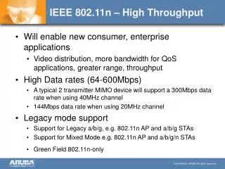
Qualcomm 802.11n PHY Design • Fully backward compatible with 802.11a/b/g • 20 MHz bandwidth with 802.11a/b/g spectral mask • OFDM based on 802.11a waveform • Optional expanded OFDM symbol (4 add’l data subcarriers) and shortened guard interval • Modulation, coding, interleaving based on 802.11a • Expanded rate set • Scalable MIMO architecture • Supports a maximum of 4 wideband spatial streams • Two forms of spatial processing • Eigenvector Steering (ES): via wideband spatial modes/SVD per subcarrier • Tx and Rx steering • Over the air calibration procedure required • Spatial Spreading (SS): modulation and coding per wideband spatial channel • No calibration required • SNR per wideband spatial stream known at Tx • Use of Eigenvector steering extends the life of low-complexity 802.11 BCC • Sustained high rate operation possible via rate adaptation • low overhead asynchronous feedback. • PHY techniques proven in FPGA-based prototype John Ketchum, et al, QUALCOMM
Code Rates and Modulation Notes: 1) short OFDM symbols; 2) expanded OFDM symbols with short guard interval John Ketchum, et al, QUALCOMM
Spatial Processing • Two forms of Spatial Processing for data transmission • Eigenvector Steering (ES): Tx attempts to steer optimally to intended Rx • Spatial Spreading (SS): Tx does not attempt to steer optimally to specific Rx • ES operating modes take advantage of channel reciprocity inherent in TDD systems • Full MIMO channel characterization required at Tx • Calibration procedure required • Tx steering using per-bin channel eigenvectors from SVD • Rx steering renders multiple Tx streams orthogonal at receiver, allowing transmission of multiple independent spatial streams • This approach maximizes data rate and range • SS Operation for partially informed transmitter • No explicit knowledge of channel or channel eigenvectors at Tx • Tx has only data rate per wideband spatial channel • Transmit full power regardless of the number of streams Tx’d • Requirement for robust CSMA operation • Maximize diversity per transmitted data stream • Minimize outage probability maximize throughput • Backwards compatible operation • Spatial spreading of data with simple unitary matrices • Cyclic diversity transmission per Tx antenna to introduce additional diversity John Ketchum, et al, QUALCOMM
Spatial Channels and Spatial Streams • ES and SS approaches result in synthesis of spatial channels, or wideband spatial channels. • Also referred to as eigenmodes, or wideband eigenmodes • On MIMO channel between a transmitting STA with NTx antennas and a receiving STA with NRx antennas, maximum of wideband spatial channels available. • Each resulting spatial channel may carry a payload, referred to as a spatial stream. • Number of spatial streams, NS, may not be greater than the Nm John Ketchum, et al, QUALCOMM
Over-the-Air Calibration • ES approach requires over-the-air calibration procedure • Compensates for amplitude and phase differences in Tx and Rx chains • Calibration required infrequently– typically on association only • Simple exchange of calibration symbols and measurement information requires little overhead and background processing • Total of ~1000 bytes of calibration data exchanged for 2x2 link • ~2800 bytes for 4x4 link John Ketchum, et al, QUALCOMM
Legacy and MIMO Training for 2, 3, and 4 Tx • STS: 802.11a STS • LTS: 802.11a LTS • SIG1: 802.11a SIGNAL • SIG2: Extended SIGNAL • MTSn: MIMO training symbol for Tx antenna n • CDx: x ns cyclic delay John Ketchum, et al, QUALCOMM
Preamble and Training Sequences • Use Standard 802.11a preamble with enhancements • Time and Frequency acquisition and AGC • Last short preamble symbol is inverted to provide improved timing reference • Cyclic delay is applied across Tx antennas • Cyclic delay applied to entire 8 µs short preamble • Cyclic delay applied to entire 8 µs long preamble • Delay increment Tcd=50 ns • Extended SIGNAL field John Ketchum, et al, QUALCOMM
Preamble and Training Sequences • MIMO Training Sequence • Orthonormal (in time) cover sequence • Walsh for 2 Tx and 4 Tx • Fourier for 3 Tx • Cyclic shift k*50 ns on Tx antenna k • Combination of orthonormal cover and cyclic shift ensures equal Rx power on all preamble symbols • Length of MIMO training sequence is always equal to the number of transmit antennas • This ensures that the receiver can always track the full channel state, and thus make fully informed rate decisions • Also ensures stable received power estimate • Two forms of MIMO Training • Steered MIMO Training Sequence supports Eigensteered operation • Direct MIMO Training Sequence supports direct channel estimation John Ketchum, et al, QUALCOMM
Feedback for ES and SS Modes • Rate adaptation • Receiving STA determines preferred rates on each of up to four wideband spatial channels • One rate per wideband spatial channel – NO adaptive bit loading • Sends one 4-bit value per spatial channel, differentially encoded, (13 bits total) to inform corresponding STA/AP of rate selections • Corresponding STA/AP uses this info to select Tx rates • Piggy-backed on out-going PPDUs • SS Mode can use single rate across all spatial streams • Channel state information • For ES operation, Tx must have full channel state information • This is obtained through exchange of transmitted training sequences that are part of PLCP header • Very low overhead. • Distributed computation of steering vectors (SVD calculation) • STAs do SVD, send resulting training sequence to AP • For SS operation, unsteered training sequences transmitted in PLCP header to support channel estimation at receiver • Feedback operates with asynchronous MAC transmissions John Ketchum, et al, QUALCOMM
Wideband Eigenmodes and OFDM • OFDM chosen so that subcarrier spacing << coherence bandwidth • Find ranked eigenmodes/eigenvalues in each OFDM subcarrier: • Ensemble of eigenmodes of a given rank across OFDM symbol comprise a wideband eigenmode • Highest ranked wideband eigenmodes exhibit very little frequency selectivity • Smallest ranked wideband eigenmode exhibits frequency selectivity of underlying channel John Ketchum, et al, QUALCOMM
Wideband Eigenmodes TGn Channel B Power is relative to average total receive power at a single antenna John Ketchum, et al, QUALCOMM
Use of Reference for Eigensteering • STAs must be calibrated to use Tx steering • MIMO training sequence part of PLCP preamble for all PPDUs • STA can compute Tx and Rx steering vectors from either steered MIMO training sequence or direct MIMO training sequence • If unsteered MIMO training sequence is used, SVD or similar is required to compute steering vectors from direct channel estimate • One STA in a corresponding pair must compute SVD from direct channel estimate • STA that does SVD sends steered MIMO training sequence in PLCP preamble of PPDU with steered data. Receiving STA uses steered MIMO training sequence to compute Rx and Tx steering • STA not computing SVD must send direct MIMO training sequence to STA computing SVD • Can be part of broadcast message such as SCHED at AP • Can be MIMO training sequence in PLCP preamble • Support of bi-directional steering with SVD calculation distributed to client STAs • Off-loads SVD from AP • Minimal complexity hit to STA John Ketchum, et al, QUALCOMM
Simulation of Spatial Multiplexing Using Tx & Rx Eigensteering • Common MIMO Training Sequence broadcast by AP once every SCAP (Scheduled Access Period) (…,t0,t3,…). Forward link (FL) channel coefficients estimated by STA receiver • FL Dedicated MIMO Training Sequence (steered) transmitted by AP at t1=0.5 ms, immediately followed by FL data PPDU • Reverse link (RL) Dedicated MIMO Training Sequence transmitted by STA at t2=1.5 ms, immediately followed by RL data PPDU • Transmit and receive steering vectors derived from most recent channel estimates • Closed-loop rate adaptation: FL and RL data rates determined based on receive SNRs observed in previous frames John Ketchum, et al, QUALCOMM
Simulation Parameters • 2x2, 4x2, and 4x4 system configurations • IEEE 802.11n channel models B, D and E • IEEE 802.11n impairment models: • Time-domain channel simulator with 5x oversampling rate (Ts=10 ns) • Rapp nonlinear power amplifier model (IM1): • Total Tx power = 17 dBm; Psat = 25 dBm • 2x2 backoff = 11 dB per PA; 4x4 backoff = 14 dB per PA • Carrier frequency offset : -13.675 PPM (IM2) • Sampling clock frequency offset: -13.675 PPM (IM2) • Phase noise at both transmitter and receiver (IM4) • 100 channel realizations generated for each SNR point • In each channel realization the Doppler process evolves over three SCAPs to allow simulation of channel estimation, closed-loop rate adaptation and FL/RL data transmission in fading conditions • Stopping criterion: 10 packet errors or 400 packets transmitted per channel realization • Targeted packet error rate performance: mean PER <= 1% John Ketchum, et al, QUALCOMM
PHY Simulation Results • What we simulated • Standard OFDM symbols • Eigenvector Steering • Spatial Spreading • Expanded OFDM symbols (52 data tones/400ns guard interval: SGI-52) • Eigenvector Steering • Spatial Spreading • PER vs SNR for Fourier channel 1×1, 2×2, 3×3, and 4×4 (CC59) • All above cases • PHY throughput and PER vs SNR; CDFs of throughput and PER • Standard OFDM symbols, ES & SS • 2×2, 4×4, and 4×2 • Channels B, D, and E • SGI-52 OFDM symbols, ES & SS • 2×2, 4×4, and 4×2 • Channel B John Ketchum, et al, QUALCOMM
PHY Simulation Results (2) • Average PER vs SNR • Standard OFDM symbols, ES & SS • 2×2, 4×4, and 4×2 • Channels B, D, and E John Ketchum, et al, QUALCOMM
Highlights of PHY Simulation Results • Highest PHY throughputs achieved in Eigenvector Steering mode • Eigenvector steering is very effective in combination with 802.11 convolutional codes • 256-QAM contributes substantially to throughput in ES mode. ES array gain overcomes effects of receiver impairments in these cases • Convolutional codes not as effective in Spatial Spreading mode • High SNR variance across subcarriers within an OFDM symbol on an SS spatial channel degrades the performance of convolutional codes • This is particularly pronounced on channel B and on link with 4 Tx and 2 Rx. • Reducing number of streams (NS < min(NTx,NRx)) reduces variance and improves overall performance. • Rate adaptation has clearly demonstrated benefits • Many cases where a given fixed rate has poor average performance, but using rate adaptation, higher overall throughput is achieved with lower PER • Part of rate adaptation is controlling the number of streams used John Ketchum, et al, QUALCOMM
Highlights of PHY Simulation Results • Use of shortened guard interval and extra data subcarriers contributes to increased throughput • Increased vulnerability to delay spread and ACI. • Improved receiver design should help with this • Optional mode can be turned off in the presence of too much delay spread • Many environments where high rates will be required, such as residential media distribution, have naturally low delay spread. John Ketchum, et al, QUALCOMM
PHY Throughput and PER Ch. B, 2×2: Eigenvector Steering John Ketchum, et al, QUALCOMM
PHY Throughput and PER Ch. B, 2×2: Spatial Spreading John Ketchum, et al, QUALCOMM
PHY Throughput and PER Ch. B, 2×2: Eigenvector Steering, SGI-52 John Ketchum, et al, QUALCOMM
PHY Throughput and PER Ch. B, 4×4 : Eigenvector Steering John Ketchum, et al, QUALCOMM
PHY Throughput and PER Ch. B, 4×4: Eigenvector Steering, SGI-52 John Ketchum, et al, QUALCOMM
PHY Throughput and PER Ch. B, 4×2 : Eigenvector Steering John Ketchum, et al, QUALCOMM