Download
1 / 38
380 likes | 498 Views
This document explores the concept of radiosity as a method for global illumination in computer graphics, particularly for diffusely reflecting surfaces. Covering key topics such as the radiosity equations, form-factor computations, and progressive refinement techniques, the text details how these approaches enhance lighting in 3D scenes. It discusses the challenges of energy balance and visibility considerations between patches, as well as optimization methods like ray casting and iterative shooting. The insights presented are essential for developing realistic rendering systems.

E N D
Radiosity Mel Slater Department of Computer Science University College London http://www.cs.ucl.ac.uk/staff/m.slater
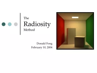
Global Illumination Approacheshttp://www.dcs.shef.ac.uk/research/groups/graphics/msc/render/TOC.HTM (a) Point light source (ray tracing), global illumination for specular surfaces. (+ textures) (b) global illumination diffuse surfaces (radiosity)... Watt A. Policarpo F. (1998) "The Computer Image" ACM Press/Addison-Wesley (c) … showing colour bleeding (+ textures)
Outline • Radiosity Equations • Form-factors and their computation • Progressive Refinement • Meshing
Radiosity Measure • It is the name of a measure of light energy... • ...and an algorithm: • Radiant energy (flux) = energy flow per unit time across a surface (watts) • Radiosity = flux per unit area (a derivative of flux with respect to area) radiated from a surface. • These are wavelength-dependent quantities.
Types of Surface Reflectance Specular-diffuse (Monte Carlo) Specular-specular (ray tracing) Diffuse-diffuse (radiosity) Diffuse-specular (Monte Carlo)
Radiosity • Models lighting in scenes for diffusely reflecting surfaces only. • Assume polygonal scene • polygons divided into n small ‘patches’ • patch i has area Ai • radiosity Bi • Emits energy Ai*Ei • Has surface reflectance pi (diffuse reflection)
Basic Equation Energy (i) = Emitted Energy (i) + Reflected Energy (i) i = 1,2,…,n Reflected Energy(i) = pi * (Total Energy in from Environment) Total Energy In (i) = Sum of proportions of energy from all other objects that reach i Fji = proportion of energy from j that reaches i per unit area of j (form-factor)
The Radiosity Equation Simplification: since
Solution of Equation • The Bi are unknown • Assume all else is known • false assumption for form-factors! • Then can be rewritten as system of n linear equations in n unknowns. • Hence patches can be rendered • ideally with smooth shading. • One set of eqns for each wavelength!
The Radiosity Equation where and
Form-factors Patch i to patch j cos cos a a Differential Form-factor F = --------------- i j dA dA 2 i j r p
Analytic Form Factors From a differential to a patch From patch to patch In practice form factors cannot be derived analytically! this follows. Must also take into account visibility between patches!
Nusselt Analog Proportion of projected area on circular base = FdAiAj Note - all patches with the same projected area have same form-factor. Form-Factor Computation
Hemi-cube Approximation Start with patch i Place a hemi-cube on its centre. Project all other patches onto this hemi-cube. The hemi-cube is ‘pixelised’, with a pre-computed for each grid and stored in a look-up table Use z-buffer for each face - storing which patches remain visible.
Delta Form-Factors Consider (eg) the top face. The exact form factor between a ‘pixel’ to the origin can be derived analytically. Same is true for all such pixels. The form-factor is approximated by sum of all delta form-factors of pixels covered by j.
y x y fj r fi x Delta Form-Factors
Problems with Hemi-Cube • Crude sampling method • more ideal would be a uniform subdivision of the hemisphere around a patch centre • more computationally intensive (has been tried). • Leads to aliasing - depending on size of ‘pixels’. • Gives form-factors (and hence radiosities) at patch centers - not ideal for smooth shading.
Use Ray Casting source Take a sample of n points on a source patch. Trace rays to a vertex on receiver patch. Sum the contributions of all visible rays. receiver
Advantages of Ray Casting • Can easily obtain the form-factors and radiosities at the vertices (smooth shading) • Can vary the sampling scheme • Visibility naturally taken into account. • See notes for the derivation and nature of the approximation.
Matrix Solution Impractical • Have been assuming the full matrix solution - impractical! • Suppose there are 10,000 polygons. • Each divided into 10 patches (say). • n = 100,000 • n2 = 10,000,000,000 • Each form factor 4 bytes (at least) • 40,000,000,000 bytes = 40Gb for the matrix.
Progressive Refinement (PR) • Solve the equation row by row, without ever storing the full matrix. • Consider again: A single term determines influence of j on i.
Progressive Refinement... Using and swapping i with j: For all patches j:
Shooting • We ‘shoot’ light out from patch i, allowing it to make a contribution to all other patches j • adjusting the radiosities of each of these other patches. • Note that the form-factors needed (Fij) are all from the ith row of the matrix - e.g., one hemicube.
Bi , DBi = 0 for all non-light sources Bi , DBi = Ei for sources. unshot radiosityDBi for each iteration { sort in descending order of BiDBi ; for each patch i { /*in the descending order*/ compute the form factors Fij using a hemi-cube at i; for each patch ji { DRad = pj * DBi * Fij * (Ai/Aj) ; DBj = DBj + DRad; Bj = Bj + DRad; } DBi = 0; } /*render scene here if desired*/ }/*until convergence of the Bi */
Ambient Term in PR • Initially images are very dark due to large amount of un-shot energy • Un-shot energy is approximated and used in an ambient term • Purely for display, does not contribute to the final solution
Average un-shot energy: Ambient Term • Average reflectance: • Take account for infinite inter-reflections:
Ambient Term • The ambient term is computed as: • For the display adjust the radiosities: • As the accuracy solution improves with each iteration, the ambient will decrease and tend to zero
Meshing • Choosing a mesh for the patches is the most problematic aspect of radiosity. • Too coarse, and sharp gradients (shadows) are missed, and the effects are blocky. • Too fine - increases time/space and oversamples for relatively low gradients. • Uniform meshing is simplest, suffers from above.
Adaptive Meshing • Only the receivers of light need to be finely subdivided • and only where there is a sharp radiosity gradient. • Use an adaptive subdivision scheme: • Subdivide patch into elements • if radiosity for the elements are slowly changing, finish • else subdivide the elements and repeat.
Substructuring • Create a coarse patch mesh. • Compute radiosity on patch mesh. • Find areas of high radiosity gradient. • Subdivide patches into elements. • Compute radiosity values on elements from the patch radiosity values. Patch boundaries Element boundaries
Substructuring • Patch to patch form factor is Fiqj= form factor between element q of patch i and j Aiq = Area of element q of patch i R = Number of elements for patch i • Radiosity of element q of patch i Biq is radiosity of element q of patch i
Substructuring • Radiosity is shot only from patches, but is computed at elements. • Only NxM form factor computations (instead of MxM) where N is the number of patches and M the number of elements. • Although the obtained solution is comparable to a MxM solution.
Meshing: Cornell Box Example using the hemi-cube method. Does not use smooth shading.
Rendering • Radiosity is a view-independent solution. • Could flat shade each patch with colour depending on radiosity at the center (bad solution!) • Instead obtain radiosities at the vertices of the polygons • use Gouraud smooth shading (interpolation) • Available very cheaply on graphics hardware.
Radiosity vs Ray-Tracing • In RT rays are send through each image pixel and followed as they reflect off objects in scene • Mostly specular surfaces • View dependent • Radiosity is based on exchange of energy between object surfaces • Diffuse surfaces • View independent • Finite elements – discreet representation of scene (mesh)
Resource and Potential Assignment www.cs.ucl.ac.uk/teaching/GMV/Exercises/radiosity/readme.html