Download

1 / 29
330 likes | 416 Views
Explore the various types of sensors used in automation systems, such as manual switches, limit switches, proximity sensors, and photoelectric sensors. Learn how sensors detect physical properties and convert them into signals for control and monitoring. Discover the essential role of sensors in modern industrial applications.

E N D
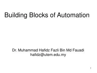
Building Blocks of Automation Dr. Muhammad Hafidz Fazli Bin Md Fauadi hafidz@utem.edu.my
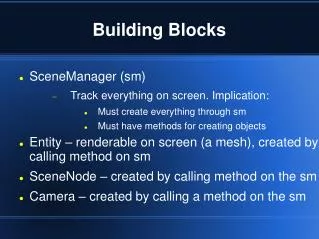
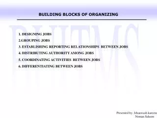
Analyzer Actuator Drive Sensor Computer Counter Timer Bar code reader Optical encoder Cylinder Solenoid Relay Motor Stepper motor DC servo motor Kinematic linkage Geneva mechanism Walking beam Manual switch Limit switch Proximity switch Photoelectric sensor
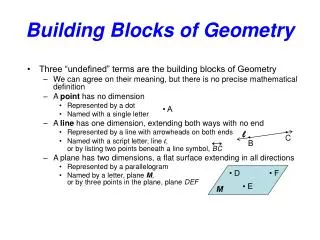
Sensor Define: device that measures a physical property and converts it into a signal which can be read by an instrument. For example, a mercury-in-glass thermometer converts the measured temperature into expansion and contraction of a liquid which can be read on a calibrated glass tube. A thermocouple converts temperature to an output voltage which can be read by a voltmeter. • Category of Sensor: • Manual switch • Limit switch • Proximity switch • Photoelectric sensor Light (light intensity) Ultrasonic (distance) Sound (db pressure) Touch
Sensor Manual switch Most people doesn’t think electric lamp switch as a sensor. But the switch is the link between the lamp and the person who desires the lamp to be turned on or off. • SPST Single pole, single throw • SPDT Single pole, double throw • DPST Double pole, single throw • DPDT Double pole, double throw
Sensor Limit switch • A switch operated by the motion of a machine part or presence of an object. • They are used for control of a machine, as safety interlocks, or to count objects passing a point. • Actuated by lever, toggle, push button, plunger, roller, ‘cat whisker’, etc. • Limit switches can be used to limit the travel of a robot arm on any of its axes of motion. Top plunger Side rotary Snap switch
Sensor Proximity switch • A proximity sensor detects the presence of objects that are nearly placed without any point of contact. • A proximity sensor often emits an electromagnetic field or a beam of electromagnetic radiation (infrared, for instance), and looks for changes in the field or return signal. • The object being sensed is often referred to as the proximity sensor's target. Different proximity sensor targets demand different sensors. • For example, a capacitive photoelectric sensor might be suitable for a plastic target; an inductive proximity sensor always requires a metal target. • Since there is no contact between the sensors and sensed object and lack of mechanical parts, these sensors have long functional life and high reliability. • The different types of proximity sensors are Inductive Proximity sensors, Capacitive Proximity sensors, Ultrasonic proximity sensors, photoelectric sensors, Hall-effect sensors, etc.
Sensor Photoelectric sensor • A photoelectric sensor, or photo eye, is a device used to detect the distance, absence, or presence of an object by using a light transmitter, often infrared, and a photoelectric receiver. • They are used extensively in industrial manufacturing. There are three different functional types: opposed (through beam), retro-reflective, and diffuse reflective sensor.
Sensor Other Sensors • Environment / Weather • Ultra Violet • Pressure • Navigation instruments • Position, angle, displacement, distance, speed, acceleration • Acoustic, sound, vibration • Chemical
Analyzer Analyzer Define: Device that analyze given data and decide the appropriate action should be taken • Computer – computers are versatile in the ways they can be programmed to manipulate data. Advancement in silicon-based technology has enabled new applications of manufacturing automation previously impossible. • Counter – device which stores (and sometimes displays) the number of times a particular event or process has occurred. Used to determine how many of various items are present or pass through an automated system. This function can be handled either internally by a computer or externally by a separate counter device. • Timer – works like alarm clock. When an elapsed time becomes equal to the preset value, an output signal is generated.
Analyzer Barcode reader • Barcode reader - electronic device for reading printed barcodes. • Like a flatbed scanner, it consists of a light source, a lens and a light sensor translating optical impulses into electrical ones. • Additionally, nearly all barcode readers contain decoder circuitry analyzing the barcode's image data provided by the sensor and sending the barcode's content to the scanner's output port
Analyzer Laser Barcode reader
Barcode Reader Technologies Pen-type readers Laser scanners - work the same way as pen type readers except that they use a laser beam as the light source and typically employ either a reciprocating mirror or a rotating prism to scan the laser beam back and forth across the bar code. Consist of a light source and photodiode that are placed next to each other in the tip of a pen or wand. CCD readers - use an array of hundreds of tiny light sensors lined up in a row in the head of the reader. Each sensor measures the intensity of the light immediately in front of it. Camera-based readers - Two-dimensional imaging scanners are the fourth and newest type of bar code reader. Use a camera and image processing techniques to decode the bar code. Omni-directional barcode scanners Omni-directional scanning uses "series of straight or curved scanning lines of varying directions that are projected at the symbol and one or more of them will be able to cross all of the symbol's bars and spaces, no matter what the orientation."
Analyzer Define: Device that analyze given data and decide the appropriate action should be taken Optical encoder - device that converts information from one format or code to another, for the purposes of standardization, speed, secrecy, security, or saving space by shrinking size using optical mechanism. http://www.ee.nmt.edu/~rhb/ee231/labs2000/lab12/lab12.html
Analyzer http://www.analog.com/static/imported-files/tutorials/MT-029.pdf
Actuator Actuator • Define: a device for moving or controlling a mechanism or system. • It is operated by a source of energy, usually in the form of an electric current, hydraulic fluid pressure or pneumatic pressure, and converts that energy into some kind of motion. • An actuator is the mechanism by which an agent acts upon an environment. The agent can be either an artificial intelligence agent or any other autonomous being (human, other animal, etc.). • An actuator is usually activated by a low-level command signal, so an amplifier may be required to provide sufficient power to drive the actuator • Types of actuator: • Robot actuator • Linear actuator • Hydraulic actuator • Pneumatic actuator Robotic actuator Linear actuator -Roller screw actuation with traveling screw Hydraulic actuator
Actuator Solenoid • A coil wound into a tightly packed helix. In physics, the term solenoid refers to a long, thin loop of wire, often wrapped around a metallic core, which produces a magnetic field when an electric current is passed through it. • Solenoids are important because they can create controlled magnetic fields and can be used as electromagnets. • The term solenoid refers specifically to a coil designed to produce a uniform magnetic field in a volume of space (where some experiment might be carried out). A- Input sideB- DiaphragmC- Pressure chamberD- Pressure relief passageE- SolenoidF- Output side
Actuator Relay • A relay is an electrically operated switch. Many relays use an electromagnet to operate a switching mechanism mechanically, but other operating principles are also used. • Relays are used where it is necessary to control a circuit by a low-power signal (with complete electrical isolation between control and controlled circuits), or where several circuits must be controlled by one signal. • The first relays were used in long distance telegraph circuits, repeating the signal coming in from one circuit and re-transmitting it to another. Relays were used extensively in telephone exchanges and early computers to perform logical operations. • A type of relay that can handle the high power required to directly control an electric motor or other loads is called a contactor. Solid-state relays control power circuits with no moving parts, instead using a semiconductor device to perform switching. • Relays with calibrated operating characteristics and sometimes multiple operating coils are used to protect electrical circuits from overload or faults; in modern electric power systems these functions are performed by digital instruments still called "protective relays".
Drives Drives Drives – device that take action upon the process at the command of an analyzer Drives vs Actuator Actuator: used to effect a short, complete, discrete motion- usually linear Drives: execute more continuous movements normally typified by rotation Actuator may turn drives on and off, and drives may provide the energy for the movement of actuator.
Drives Stepper motor stepper motor (or step motor) is a brushless DC electric motor that divides a full rotation into a number of equal steps. The motor's position can then be commanded to move and hold at one of these steps without any feedback sensor (an open-loop controller), as long as the motor is carefully sized to the application. Animation of a simplified stepper motor (unipolar)Frame 1: The top electromagnet (1) is turned on, attracting the nearest teeth of the gear-shaped iron rotor. With the teeth aligned to electromagnet 1, they will be slightly offset from right electromagnet (2).Frame 2: The top electromagnet (1) is turned off, and the right electromagnet (2) is energized, pulling the teeth into alignment with it. This results in a rotation of 3.6° in this example.Frame 3: The bottom electromagnet (3) is energized; another 3.6° rotation occurs.Frame 4: The left electromagnet (4) is energized, rotating again by 3.6°. When the top electromagnet (1) is again enabled, the rotor will have rotated by one tooth position; since there are 25 teeth, it will take 100 steps to make a full rotation in this example.
Drives DC servo motor • Servomotors vs. stepper motors • Servomotors are generally used as a high performance alternative to the stepper motor. Stepper motors have some inherent ability to control position, as they have inbuilt output steps. • This often allows them to be used as an open-loop position control, without any feedback encoder, as their drive signal specifies the number of steps of movement to rotate. • This lack of feedback though limits their performance, as the stepper motor can only drive a load that is well within its capacity, otherwise missed steps under load may lead to positioning errors. • The encoder and controller of a servomotor are an additional cost, but they optimise the performance of the overall system (for all of speed, power and accuracy) relative to the capacity of the basic motor. • With larger systems, where a powerful motor represents an increasing proportion of the system cost, servomotors have the advantage. • Many applications, such as laser cutting machines, may be offered in two ranges, the low-priced range using stepper motors and the high-performance range using servomotors.
Drives Kinematic linkage - Geneva mechanism • The Geneva wheel, or Maltese cross, is a cam like mechanism that provides intermittent rotary motion & is widely used in both low and high-speed machinery. • Although originally developed as a stop to prevent over winding of watches, it is now extensively used in automatic machinery, e.g. where a spindle, turret, or worktable must be indexed.
ns-Slotted driven member Driver Fig 3 Fig 2 Fig 1 • Several mechanisms are available to provide rotational indexing motion for dial indexing machine. • Two representative types include: • Cam Drive • Geneva Mechanism
Working Principle • Geneva Mechanism uses a continuously rotating driver to index a table through a partial rotation. • If the driven member has six slots for a six-station dial indexing table, each turn of the driver results in 1/6 rotation of the table or 360o/6 slots = 60o. • The driver only causes motion of the table through a portion of its own rotation.
Given the rotational speed of the driver, we can obtained total cycle time as: • For a six-slotted Geneva, 120o of driver rotation is to index the table. • The remaining 240o of the driver rotation is dwell time for the table, during which the processing operation must be completed on the work unit. In general,
The dwell time @ available service time per cycle is given by: The indexing time is given:
1 2 3 4 example A rotary worktable is driven by a Geneva Mechanism with six slots, as in Fig 4. The driver rotates at 30 rev/min. Determine the cycle time, available process time and the lost time each cycle indexing the table. Fig 4
Formula for dwell time, Ts is Given that Ts = 2.5 seconds = 0.0416 minutes exercise A Geneva with six slots is used to operate the worktable of a dial indexing machine. The slowest workstation on the dial indexing machine has an operation time of 2.5 seconds, so the table must be in a dwell position for this length of time. At what rotational speed must the driven member of the Geneva mechanism be turned to provide this dwell time (in rpm)?
Kinematic linkage - Walking Beam Drives • A mean of intermittently indexing a linear type of automated line and are thus analogous to the Geneva used to drive rotary indexing table. • Driven by actuating cylinder • Advantage: permit arbitrary setting of index and dwell times by varying cylinder stroke and return times. • Constant rotating crank can also be used. • Typically noisy and can damage the manufactured part by dropping the line onto the rest. • More flexible compared to Geneva. Watch!! http://www.youtube.com/watch?v=NdmSdFi7CkI