Download
1 / 24
240 likes | 391 Views
Waller Creek 8 th Street Side Weir CFD Modeling and Simulation. Preliminary Results. Scenario 4. September 1, 2009. ALDEN Research Laboratory Inc. 30 Shrewsbury St., Holden, MA 01520. Iso-surface plot of water colored with velocity magnitude.

E N D
Waller Creek 8th Street Side Weir CFD Modeling and Simulation Preliminary Results Scenario 4 September 1, 2009 ALDEN Research Laboratory Inc. 30 Shrewsbury St., Holden, MA 01520
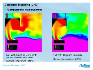
Iso-surface plot of water colored with velocity magnitude (solid component is transparent to see the water surface) * velocity magnitude color scale shows the actual range of velocity values throughout the system (ft/s)
Iso-surface plot of water colored with velocity magnitude (solid component is not shown to see clearly the water surface) * velocity magnitude color scale shows the actual range of velocity values throughout the system (ft/s)
Iso-surface plot of water colored with free surface elevation (Plan view) (ft)
Iso-surface plot of water colored with free surface elevation (showing water surface elevation in the building) (ft)
Iso-surface plot of water colored with free surface elevation (showing water surface elevation downstream of inline weir) * note the color scale range: 458 ft. to 460 ft. (ft)
Plot of velocity contour with vectors (slice plane cut at elevation 457 ft.)
Plot of velocity contour with vectors (slice plane cut at elevation 457 ft.)
Plot of velocity contour with vectors (slice plane cut at elevation 455 ft.)
Plot of velocity contour with vectors (slice plane cut at elevation 455 ft.)
Plot of velocity contour (slice plane cut vertically at different locations.)
Plot of velocity contour with vectors (slice plane cut at elevation 445 ft.)
Plot of velocity contour with vectors (slice plane cut at elevation 445 ft.) * same with slide 12 except walls were removed for clear view under the net deck.
Plot of velocity contour with vectors (slice plane cut at elevation 445 ft.) * same with slide 13 with different color scale.
Plot of velocity contour with vectors (slice plane cut at elevation 445 ft.) * closer look at the building
Plot of velocity contour with vectors (slice plane cut at elevation 445 ft.) * same with slide 15 with different color scale.
Velocity contour plot of water at the entrance of each bay Average velocity, V = 6.96 ft/s Volume flow rate, Q = 205 cfs Average velocity, V = 7.72 ft/s Volume flow rate, Q = 147 cfs Average velocity, V = 12.69 ft/s Volume flow rate, Q = 343 cfs
Velocity contour plot of water at the entrance of each bay (streamlines are shown entering the building)
Plot of streamlines colored with velocity magnitude (plan view)
Plot of streamlines colored with velocity magnitude (isometric view)
Plot of streamlines colored with velocity magnitude (isometric view)
Plot of streamlines colored with velocity magnitude (isometric view)
Plot of streamlines colored with velocity magnitude (plan view)
Plot of streamlines colored with velocity magnitude (plan view)