I. Floorplanning with Fixed Modules
I. Floorplanning with Fixed Modules. Fixed modules only, no rotation allowed m 1 (4,5), m 2 (3,7), m 3 (6,4), m 4 (7,7). ILP Formulation. Non-Overlapping Constraints (cont). Additional Constraints. Solutions. Using GLPK we get the following solutions:. Final Floorplan.

I. Floorplanning with Fixed Modules
E N D
Presentation Transcript
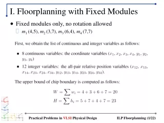
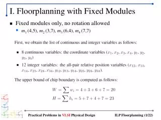
I. Floorplanning with Fixed Modules • Fixed modules only, no rotation allowed • m1 (4,5), m2 (3,7), m3 (6,4), m4 (7,7) Practical Problems in VLSI Physical Design
ILP Formulation Practical Problems in VLSI Physical Design
Non-Overlapping Constraints (cont) Practical Problems in VLSI Physical Design
Additional Constraints Practical Problems in VLSI Physical Design
Solutions • Using GLPK we get the following solutions: Practical Problems in VLSI Physical Design
Final Floorplan • Why the non-optimality? • Due to linear approximation of area objective (= y*) • Chip width/height constraints also affected • In fact, our ILP solution (y* = 12) is optimal under these conditions. Practical Problems in VLSI Physical Design
II. Floorplanning with Rotation • Fixed modules, rotation allowed • Fixed modules: m1 (4,5), m2 (3,7), m3 (6,4), m4 (7,7) • Need 4 more binary variables for rotation: z1, z2, z3, z4 • We use M = max{W,H} = 23 Practical Problems in VLSI Physical Design
ILP Formulation Practical Problems in VLSI Physical Design
Non-Overlapping Constraints (cont) Practical Problems in VLSI Physical Design
Non-Overlapping Constraints (cont) Practical Problems in VLSI Physical Design
Additional Constraints Practical Problems in VLSI Physical Design
Solutions • Using GLPK we get the following solutions: Practical Problems in VLSI Physical Design
III. Floorplanning with Flexible Modules • 2 Fixed modules: • m1 (4,5), m2 (3,7) (rotation allowed) • 2 Flexible modules: • m3: area = 24, aspect ratio [0.5, 2] • m4: area = 49, aspect ratio [0.3, 2.5] Practical Problems in VLSI Physical Design
Linear Approximation Practical Problems in VLSI Physical Design
Linear Approximation (cont) Practical Problems in VLSI Physical Design
Upper Bound of Chip Dimension Practical Problems in VLSI Physical Design
Non-Overlap Constraint Practical Problems in VLSI Physical Design
Non-Overlap Constraint (cont) Practical Problems in VLSI Physical Design
More Constraints Practical Problems in VLSI Physical Design
Solutions Practical Problems in VLSI Physical Design
Comparison • Fixed modules only = 12 × 12 • Rotation allowed = 11 × 11 • Flexible modules used = 10.46 × 10.32 Practical Problems in VLSI Physical Design
Approximation Error and Overlap • Due to linear approximation • Approximated area of m3 = 3.46 × 5.2 = 17.99 (actually 24) • Approximated area of m4 = 3.83 × 7.32 = 28.04 (actually 49) • Real area of m3 = 3.46 × 6.94 = 24 • Real area of m4 = 3.83 × 12.79 = 49 • Floorplan area increases, overlap occurs Practical Problems in VLSI Physical Design