Download
1 / 28
280 likes | 377 Views
UPDATE ON THE FORWARD PROTON DETECTOR. Gilvan Alves Lafex/CBPF. Introduction Accelerator Roman Pots Detector Future Plans. April 1, 1998 (no kidding). FORWARD PROTON DETECTOR. Roman Pot. Bellows. p. p. Detector. A 1Q. P 1Q. A 1S. P 1S. S. D. Q 1. Q 2. Q 3. Q 4.

E N D
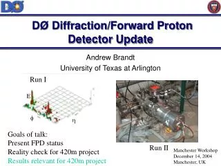
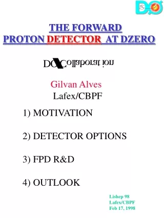
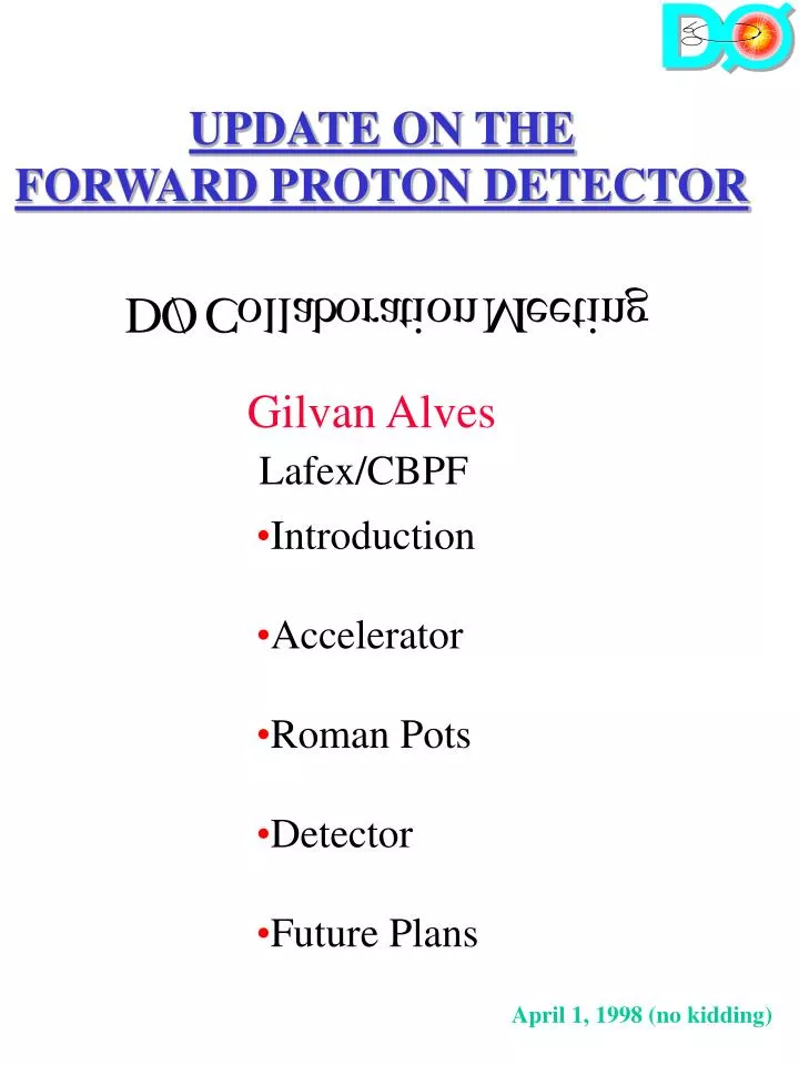
UPDATE ON THE FORWARD PROTON DETECTOR Gilvan Alves Lafex/CBPF • Introduction • Accelerator • Roman Pots • Detector • Future Plans April 1, 1998 (no kidding)
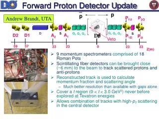
FORWARD PROTON DETECTOR Roman Pot Bellows p p Detector A1Q P1Q A1S P1S S D Q1 Q2 Q3 Q4 Q4 Q3 Q2 S A2Q A2S P2S P2Q AD2 AD1 59 57 36 31 23 19 13 7 0 7 13 19 23 31 Z(m) Series of 18 Roman Pots forms 9 independent spectrometers 1 Dipole Spectrometer ( p ) x > xmin 8 Quadrupole Spectrometers (p or p, up or down, left or right) t > tmin
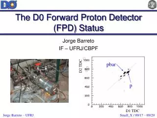
pBeam pF P p p Diffractive Kinematics • Rapidity Gap Approach • Need to Tag and Measure p( p ) p Detector
Y - Pot 14.4mm 20mm X - Pot 6.8mm Beam Axis 8s Beam Envelope The Detector UVX Planes 0.8mm
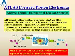
PROPOSAL FOR A FORWARD PROTON DETECTOR AT DZERO (P-900) Andrew Brandt FNAL/ 1) PHYSICS MOTIVATION 2) FPD DETAILS Fermilab PAC meeting Fermilab October 17, 1997
ACCELERATOR MODIFICATIONS 1) Move low beta quadrupoles ~ 2/3 meter closer to the interaction point. Requires modified quadrupole supports. 2) Insert pots in electrostatic separator region. Requires bypass extension. Bypass extended
ACCELERATOR MODIFICATIONS • 3) Dipole Spectrometer does not require • modifications Warm section exists. • Feasibility and Cost Studies done in conjunction with Beams Division (see Memo). • No interference with Tevatron operation • Total Cost $500k (Mostly Engineering Labor). • An Engineer from Brazil will work with the AD on the modifications. • Mike Martens has joined the FPD group and will act as the Beams Division Liaison Person for this project.
FRONT VIEW OF PROPOSED ROMAN POTS
Full Scale Model Presented at Lishep98 - Rio
Full Scale Model Presented at Lishep98 - Rio
Full Scale Model Presented at Lishep98 - Rio
Further Development in Progress • Reducing Pot “Long Neck” Size • Interface with Pumping Devices • Chainless Design • Agreement Signed with LNLS for • Prototype building this spring • LNLS - National Synchrotron Lab • Helps on Funding • Prague group is Helping with • design & Vacuum expertise
THE DETECTOR Six planes (u,u’,v,v’,x,x’) of 800 m scintillator fibers (’) planes offset by 2/3 fiber 20 channels/plane(U,V)’ 16 channels/plane(X,X’) 112 channels/detector 2016 total channels 80 m theoretical resolution
THE DETECTOR 4 Fiber bundle fits well the pixel size of H6568 16 Ch. MAPMT 7 PMT’s/detector (most of the cost) U’ U
Photon Detection Device • Quantum Efficiency • Light Charge • VLPC ( 80%) • APD ( 70%) • Image Intensifier • CCD ( 20%) • Low rate • MAPMT ( 20%) • VLPC the best option • But... cryogenics$$$
DETECTOR OPTIONS • Fiber Options Investigated • Scint. Tile to Clear Fiber • Scint. Tile to WLS Fiber • Scint. Fiber Straight • Scint. Fiber to Clear Fiber • Round vs. Square Fibers
Scint Tile 800m thick WLS fiber DETECTOR OPTIONS 4fibers PMT Scint Tile 800m thick Clear Fiber 2 WLS fibers PMT
Scint Fibers 800m Clear fiber DETECTOR OPTIONS Mirrored side 4fibers PMT Scint Fibers 800m Mirrored side 4fibers PMT
Detector Test Setup Use 10644Ru 3.5 MeV e- Source D Source Collimator T2 T1 D - Detector Cell T1&T2 - Trigger Scintillators
Single PE Measurement H6568 LED Calibration. Scint. Tile + Clear Fiber <NPE>=3.0
Scint. Fiber Output H6568 <NPE>=7.3 Effect of cutting Fiber at 45 <NPE>=6.8
<NPE>=7.4 Scint. Fiber + Clear Fiber Output H6568 • Similar to Uncut Straight Fibers • Gain Attenuation length • Losses due to • Cutting Fiber at 45 (5%) • Fiber Splicing (5-10%) • Preferred Option • Accelerator Background • Cross Talk
Current Developments • 0th order Fiber detector Prototype being tested • DAQ for prototype testing has been assembled • Modifications to Splicing Machine being made • Work on adapting CFT Trigger System • Work on FPD Trigger strategy in progress
1998 Plans • Finalizing Detector and Pot Designs • BothPrototypes Ready by Fall • Request for National Grant within Brazil • Project Integration within accelerator and D