Understanding First Hop Redundancy Protocols
730 likes | 1.44k Views
Understanding First Hop Redundancy Protocols. Introduction to First Hop Redundancy. Proxy ARP Static Default Gateway HSRP VRRP GLBP. Proxy ARP. Legacy solution. Enabled by default. Used before default gateways were supported on IP clients.

Understanding First Hop Redundancy Protocols
E N D
Presentation Transcript
Introduction to First Hop Redundancy • Proxy ARP • Static Default Gateway • HSRP • VRRP • GLBP
Proxy ARP • Legacy solution. • Enabled by default. • Used before default gateways were supported on IP clients. • End station acts as if destination were on same network segment. • Relatively slow due to reliance on aging out of ARP cache.
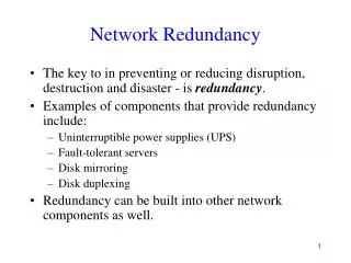
Static Default Gateway • Not dynamic. • Does not provide secondary path.
Hot Standby Router Protocol (HSRP) • Cisco-proprietary gateway redundancy protocol. • Participating routers talk to each other and agree on a virtual router with a virtual IP address which end systems use as a default gateway.
HSRP Failover • When active router or links between routers fail, the standby router stops seeing hello messages from active router. Standby router then assumes role of forwarding router. • Because new forwarding router assumes both IP and MAC address of virtual router, end stations see no disruption in service.
HSRP Operation • HSRP active and standby routers send hello messages to multicast address 224.0.0.2 UDP port 1985. • Hello messages used to communicated between routers within HSRP group. • All routers in HSRP group need to be L2-adjacent. • All routers in an HSRP group have specific roles and interact in specific ways: • Virtual router • Active router • Standby router • Other routers
HSRP MAC Address • Router A assumes the active role and forwards all frames addressed to the assigned HSRP MAC address of 0000.0c07.acxx, where xx is the HSRP group identifier.
HSRP Active Router and Spanning Tree Topology • In a redundant spanning-tree topology, some links are blocked. The spanning-tree topology has no awareness about the HSRP configuration. There is no automatic relationship between the HSRP active router election process and the Spanning Tree Root Bridge election. • When configuring both spanning tree and HSRP (or any other first hop redundancy protocol), you must make sure that the active router is the same as the root bridge for the corresponding VLAN. When the root bridge is different from the HSRP active router, a suboptimal path can result, as illustrated.
Configuring HSRP • Configure HSRP on the interface. Switch(config-if)# standby group-number ip ip-address The group number is optional and indicates the HSRP group to which this interface belongs. Specifying a unique group number in the standby commands enables the creation of multiple HSRP groups. The default group is 0. The IP address is that of the virtual router IP address for the HSRP group.
Configuring HSRP Priority and Preempt • To set the HSRP priority value of a router, enter this command in interface configuration mode: standby group-numberprioritypriority-value • The priority value can be from 0 to 255. The default value is 100. • During the election process, the router with the highest priority in an HSRP group becomes the active router. If a tie occurs, the router with the highest configured IP address becomes active. • If the routers do not have preempt configured, a router that boots up significantly faster than the others in the standby group becomes the active router, regardless of the configured priority. The former active router can be configured to resume the forwarding router role by preempting a router with a lower priority. • To enable a router to resume the forwarding router role, enter this command in interface configuration mode: standby [group-number] preempt [delay {minimumsecondsreloadsecondssyncseconds}]
HSRP Configuration Example • Routers A and B are configured with priorities of 110 and 90, respectively. The configuration of Router A is displayed. • The preempt keyword ensures that Router A will be the HSRP active router as long its interface is active. RouterA(config)# interface vlan 10 RouterA(config-if)# ip address 10.1.1.2 255.255.255.0 RouterA(config-if)# standby 10 ip 10.1.1.1 RouterA(config-if)# standby 10 priority 110 RouterA(config-if)# standby 10 preempt
HSRP Authentication Example • HSRP authentication prevents rogue routers on the network from joining the HSRP group. HSRP authentication is enabled by configuration of an authentication string on all member devices of the HSRP group. • The authentication string is a maximum of 8 characters and the default keyword is cisco. RouterA(config)# interface vlan 10 RouterA(config-if)# ip address 10.1.1.2 255.255.255.0 RouterA(config-if)# standby 10 ip 10.1.1.1 RouterA(config-if)# standby 10 priority 110 RouterA(config-if)# standby 10 preempt RouterA(config-if)# standby 10 authentication xyz123
HSRP Timers Configuration Example RouterA(config)# interface vlan 10 RouterA(config-if)# ip address 10.1.1.2 255.255.255.0 RouterA(config-if)# standby 10 ip 10.1.1.1 RouterA(config-if)# standby 10 priority 110 RouterA(config-if)# standby 10 preempt RouterA(config-if)# standby 10 authentication xyz123 RouterA(config-if)# standby 10 timers msec 200 msec 750 RouterA(config-if)# standby 10 preempt delay minimum 225
HSRP Versions • HSRP version 1 is the default in IOS and it enables group numbers up to 255. Because one can have up to 4095 VLANs, one has to reuse the same HSRP group number on multiple interfaces if needed. This is allowed even though it might cause some confusion. • HSRPv1 uses the Virtual MAC address of the form 0000.0C07.ACXX (XX = HSRP group), and the HSRPv1 hello packets are sent to multicast address 224.0.0.2. • HSRP version 2 has been added to IOS since 12.2 46SE or later and it enables group numbers up to 4095. This enables you to use the VLAN number as the group number. • With HSRPv2, the MAC address of the virtual router and the multicast address for the hello messages has been changed. The virtual MAC address is 0000.0C9F.FXXX (XXX=HSRP group), and hello packets are sent to multicast address 224.0.0.102. • Also, HSRPv2 has a different packet format from HSRPv1. Ensure that the same version is configured on all routers in a HSRP group. Otherwise hello messages are not understood. Version 1 is the default. • Use the following command to change the version: Switch(config-if)# standby <hsrp group number> version 2
HSRP Interface Tracking (1) • Enables priority of standby group router to be automatically adjusted based on availability of tracked interfaces. • When tracked interface becomes unavailable, HSRP priority is decreased. • Ensures the router with unavailable interface relinquishes active router role.
HSRP Interface Tracking (2) • Configure interface tracking. Switch(config-if) standby [group-number] trackinterface-typeinterface-number[interface-priority]
HSRP Interface Tracking (3) To configure HSRP with interface tracking, follow these steps: • Step 1. Configure the standby group. • Step 2. Configure priority (default 100). • Step 3. Configure preempt on all devices within the HSRP group. • Step 4. Configure the tracked interfaces and decrement (default decrement 10).
HSRP Interface Tracking (4) SW4(config)# interface vlan 10 SW4(config-if)# ip address 10.1.1.2 255.255.255.0 SW4(config-if)# standby 10 ip 10.1.1.1 SW4(config-if)# standby 10 priority 110 SW4(config-if)# standby 10 preempt SW4(config-if)# standby 10 track fastethernet0/23 20 SW4(config-if)# standby 10 track fastethernet0/24
Multiple HSRP Groups (1) • HSRP allows for only one active router in the same subnet. In a typical network, engineers would want to use all available routers to load share the traffic going across the network. Multigroup HSRP enables routers to simultaneously provide redundant backup and perform load sharing across different IP subnets. • In the figure, two HSRP-enabled routers participate in two separate VLANs, using 802.1Q. Running HSRP over trunks enables users to configure redundancy among multiple routers that are configured as front ends for VLAN IP subnets.
HSRP Monitoring (1) • Use the show standby family of commands to verify HSRP state. Several arguments can be used. • The show standby brief command displays a summary of the HSRP configurations. • For each standby group, you can verify the local router neighbors. Switch# show standby brief P indicates configured to preempt. | Interface Grp Pri P State Active Standby Virtual IP Vl10 10 120 P Active local 10.1.10.3 10.1.10.1 Vl20 20 90 P Standby 10.1.20.3 local 10.1.20.1 Switch#show standby neighbor vlan10 HSRP neighbors on Vlan10 10.1.10.3 Active groups: 10 No standby groups
HSRP Monitoring (2) Switch# show standby Vlan10 - Group 10 State is Active Virtual IP address is 10.1.10.1 Active virtual MAC address is 0000.0c07.ac0a Local virtual MAC address is 0000.0c07.ac0a (v1 default) Hello time 3 sec, hold time 10 sec Next hello sent in 1.248 secs Preemption enabled Active router is local Standby router is 10.1.10.3, priority 90 (expires in 10.096 sec) Priority 120 (configured 120) Track interface Port-channel31 state Up decrement 30 Track interface Port-channel32 state Up decrement 30 Group name is “hsrp-Vl10-10” (default) Vlan20 - Group 20 State is Standby Virtual IP address is 10.1.20.1 Active virtual MAC address is 0000.0c07.ac14 Local virtual MAC address is 0000.0c07.ac14 (v1 default) Hello time 3 sec, hold time 10 sec Next hello sent in 2.064 secs Preemption enabled Active router is 10.1.10.3, priority 120 (expires in 10.032 sec) Standby router is local Priority 90 (configured 90) Group name is “hsrp-Vl20-20” (default) When simply typing show standby, a complete display is provided.
HSRP Monitoring (3) • The IP address and corresponding MAC address of the virtual router are maintained in the ARP table of each router in an HSRP group. • The command show ip arpdisplays the ARP cache on a multilayer switch.
VRRP Scenario • Routers A, B, and C are members of a VRRP group. The IP address of the virtual router is the same as that of the LAN interface of Router A (10.0.0.1). Router A is responsible for forwarding packets sent to this IP address. • The clients have a gateway address of 10.0.0.1. Routers B and C are backup routers. If the master router fails, the backup router with the highest priority becomes the master router. When Router A recovers, it resumes the role of master router.
VRRP Configuration Example (1) RouterA# configure terminal Enter configuration commands, one per line. End with CNTL/Z. RouterA(config)# interface vlan 1 RouterA(config-if)# ip address 10.0.2.1 255.255.255.0 RouterA(config-if)# vrrp 1 ip 10.0.2.254 RouterA(config-if)# vrrp 1 timers advertise msec 500 RouterA(config-if)# end RouterB# configure terminal Enter configuration commands, one per line. End with CNTL/Z. RouterB(config)# interface vlan 1 RouterB(config-if)# ip address 10.0.2.2 255.255.255.0 RouterB(config-if)# vrrp 1 ip 10.0.2.254 RouterB(config-if)# vrrp 1 priority 90 RouterB(config-if)# vrrp 1 timers learn RouterB(config-if)# end
VRRP Configuration Example (2) RouterA# show vrrp interface vlan 1 Vlan1 - Group 1 State is Master Virtual IP address is 10.0.2.254 Virtual MAC address is 0000.5e00.0101 Advertisement interval is 0.500 sec Preemption is enabled min delay is 0.000 sec Priority is 100 Master Router is 10.0.2.1 (local), priority is 100 Master Advertisement interval is 0.500 sec Master Down interval is 2.109 sec RouterB# show vrrp interface vlan 1 Vlan1 - Group 1 State is Backup Virtual IP address is 10.0.2.254 Virtual MAC address is 0000.5e00.0101 Advertisement interval is 0.500 sec Preemption is enabled min delay is 0.000 sec Priority is 90 Master Router is 10.0.2.1, priority is 100 Master Advertisement interval is 0.500 sec Master Down interval is 2.109 sec (expires in 1.745 sec)
GLBP Functions (1) • GLBP active virtual gateway (AVG):Members of a GLBP group elect one gateway to be the AVG for that group. Other group members provide backup for the AVG if the AVG becomes unavailable. The AVG assigns a virtual MAC address to each member of the GLBP group. • GLBP active virtual forwarder (AVF): Each gateway assumes responsibility for forwarding packets that are sent to the virtual MAC address assigned to that gateway by the AVG. These gateways are known as AVFs for their virtual MAC address. • GLBP communication: GLBP members communicate between each other through hello messages sent every 3 seconds to the multicast address 224.0.0.102, User Datagram Protocol (UDP) port 3222.
GLBP Functions (2) • Router A is acting as the AVG. Router A has assigned virtual MAC 0007.b400.0101 to itself. • Router B is acting as AVF for the virtual MAC 0007.b400.0102 assigned to it by Router A. • Client 1 default gateway is Router A. • Client 2 default gateway is Router B based on the virtual MAC assignment.
GLBP Features • Load sharing: You can configure GLBP in such a way that multiple routers can share traffic from LAN clients, thereby sharing the traffic load more equitably among available routers. • Multiple virtual routers: GLBP supports up to 1024 virtual routers (GLBP groups) on each physical interface of a router and up to four virtual forwarders per group. • Preemption: The redundancy scheme of GLBP enables you to preempt an AVG with a higher priority backup virtual gateway that has become available. Forwarder preemption works in a similar way, except that forwarder preemption uses weighting instead of priority and is enabled by default. • Efficient resource utilization: GLBP makes it possible for any router in a group to serve as a backup, which eliminates the need for a dedicated backup router because all available routers can support network traffic.
GLBP Operations (1) Operational modes for load balancing: • Weighted load-balancing algorithm: The amount of load directed to a router is dependent upon the weighting value advertised by that router. • Host-dependent load-balancing algorithm: A host is guaranteed use of the same virtual MAC address as long as that virtual MAC address is participating in the GLBP group. • Round-robin load-balancing algorithm: As clients send ARP requests to resolve the MAC address of the default gateway, the reply to each client contains the MAC address of the next possible router in round-robin fashion. All routers’ MAC addresses take turns being included in address resolution replies for the default gateway IP address.
GLBP Operations (2) • By default, GLBP attempts to balance traffic on a per-host basis using the round-robin algorithm. • When a client sends an ARP message for the gateway IP address, the AVG returns the virtual MAC address of one of the AVFs. • When a second client sends an ARP message, the AVG returns the next virtual MAC address from the list.
GLBP Operations (3) • Having each resolved a different MAC address for the default gateway, Clients A and B send their routed traffic to separate routers, although they both have the same default gateway address configured. • Each GLBP router is an AVF for the virtual MAC address to which it has been assigned.
GLBP Interface Tracking (1) • Like HSRP, GLBP can be configured to track interfaces. • The WAN link from Router R1 is lost. GLBP detects the failure. Just like HSRP, GLBP decrements the gateway priority when a tracked interface fails. The second gateway then becomes primary. This transition is transparent for the LAN client.
GLBP Interface Tracking (2) • Because interface tracking was configured on R1, the job of forwarding packets for virtual MAC address 0000.0000.0001 will be taken over by the secondary virtual forwarder for the MAC, Router R2. Therefore, the client sees no disruption of service nor does the client need to resolve a new MAC address for the default gateway.
GLBP Interface Tracking (3) • SW4 is forwarding. Its initial weight (or priority) is 110. • SW4 tracks both Fa0/23 and Fa0/24 interfaces. Fa0/23 is the active interface. Losing fa0/23 decrements SW4 by 20 points, thus bringing SW4’s weight down (from 110) to 90. Fa0/24 is a backup interface. • Losing Fa0/24 decrements SW4 by 10 points, thus bringing SW4’s weight down (from 110) to 100, which is the default weight of the other routers. • Losing both Fa0/23 and Fa0/24 brings SW4’s weight down (from 110) to 80.