Download
1 / 17
170 likes | 275 Views
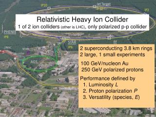
Relativistic Heavy Ion Collider 1 of 2 ion colliders (other is LHC) , only polarized p-p collider. 2 superconducting 3.8 km rings 2 large, 1 small experiments 100 GeV/nucleon Au 250 GeV polarized protons Performance defined by 1. Luminosity L 2. Proton polarization P

E N D
Relativistic Heavy Ion Collider1 of 2 ion colliders(other is LHC), only polarized p-p collider 2 superconducting 3.8 km rings 2 large, 1 small experiments 100 GeV/nucleon Au 250 GeV polarized protons Performance defined by 1. Luminosity L 2. Proton polarization P 3. Versatility (species, E) 1
RHIC heavy ions – luminosity evolution to date <L> = 15x design in 2011 • About 2x increase in Lint/week each • Run-4 to Run-7 • Run-7 to Run10 • Run-10 to Run-11 • Rate of progress will slow down – burn off 50% of beam in collisions already LNN = L N1N2 (= luminosity for beam of nucleons, not ions) 2
RHIC – effect of stochastic cooling in 2011 luminosity in 2 consecutive stores Factor 2 gain in averageluminosity from stochasticcooling so far – add horizontalcooling for Run-12 40ns with long. and vert. stochastic cooling w/o cooling w/o with cooling strong transverse cooling makes longitudinal cooling less efficient, i.e. these longitudinal profiles at the end of a store with be more pronounced with horizontal cooling next year [hourglass factor 0.75 at beginning, 0.55 at end of store] 3
56 MHz SRF for heavy ions – under construction (I. Ben-Zvi et al.) Commissioning planned for 2014 • Longitudinal profile at end of store • even with cooling ions migrate into neighboring buckets • can be reduced with increased longitudinal focusing 40 ns 40ns Average luminosity vs. vertex size + 56 MHz SRF full 3D cooling • l/4 Ni resonator • common to both beams • beam driven • 56 MHz, 2 MV demonstrated 2011 long. + ver. cooling Calculations Calculation by M. Blaskiewicz 4
RHIC heavy ions – other luminosity limits • Operate close to a number of other limits: • Instabilities on ramp at transition (gtr = 26) driven by machine impedance and electron cloud • Beam loading during rf rebucketinglimit removed last summer by separating common storage cavities • Intensity limit of beam dump (quench Q4)limit removed last summer by inserting sleeves in beam dump pipe • Bunch intensity limit from injector chain injected Nb = 1.5x10⁹ in Run-11 • Chromatic aberrations with small b*about 50% of particle loss due to burn-off, other 50% largely due to off-momentum dynamic aperture tested b* squeeze in store after cooling to equilibrium at limit in 2007 at limit in 2010 at limit in 2010 at limit in 2011 Above list changes from year to year as most limiting effects are mitigated. 5
Electron Beam Ion Source (EBIS) (J. Alessi et al.) • 10 A electron beam creates desired charge state(s) in trap within 5 T superconducting solenoid • Accelerated through RFQ and linac, injected into AGS Booster • All ion species incl. noble gas, uranium and polarized 3He • Operated for NSRL with • He+, He2+, Ne5+,Ne8+, Ar11+, Ti18+,Fe20+ • Commissioning for RHICRun-12 under way • Work on ~2x Au32+increaseto design intensity(from transmission) • Received U cathode 6
Au-Au energy scan to date Peak and average luminosities fall faster than 1/g2 at lowest energiesNeed cooling at low energies to significantly increase luminosities 7
e-cooling for low energy collider operation (A. Fedotov et al.) • Fermilab Pelletron(cooled 8 GeV pbar for Tevatron use) usable – scheduled for decommissioning in 3/2012, so far have not requested transfer Cooling into space charge limit DQsc~ 0.05(new collider regime) with cooling Expect up to factor 5more integrated luminosity(depending on energy and DQsc) A. Fedotov et al.HB 2008 without cooling 8
RHIC polarized protons – luminosity and polarization At 250 GeV in 2011 Lavg = 90x1030cm-2s-1 Pavg = 48% Lavg +60% rel. to 2009 Pavg+40% rel. to 2011 FOM = LP4(longitudinally polarized beams) 9
AnDY in 2011 (250 GeV pp) • Beam envelope function b* = 3.0 m at IP2 • Reduced IP2 crossing angle from initially 2.0 mrad to zero • Added 3rd collision with following criteria: • Nb ≤ 1.5x10¹¹ • Beam loss rate <15%/h in both beams • Not before first polarization measurement 3h into store x/IP = 0.005 visible impact, few percent loss to STAR/PHENIX small impact x/IP = 0.004 PHENIX STAR loss rates AnDY 10
Optically Pumped Polarized H– source (OPPIS) – A. Zelenski Upgraded OPPIS (2013) • Goals:1. H− beam current increase to 10mA(order of magnitude)2. Polarization to 85-90%(~5% increase) • Upgrade components: • 1. Atomic hydrogen injector (collaboration with BINP Novosibirsk) • 2. Superconducting solenoid (3 T) • 3. Beam diagnostics and polarimetry Source Neutralizer Ionizer Rb-cell Sona Na-jet (H+) (H0) (H+) (H0) (H−) sc solenoid 10x intensity increase was demonstrated in a pulsed operation by using a very high-brightness Fast Atomic Beam Source instead of the ECR source Superconducting solenoid delayed – may have impact oncommissioning schedule. 11
Electron lenses – partial head-on beam-beam compensation • Polarized proton luminosity limited by head-on beam-beam effect (DQbb,max ~ 0.02) • Basic idea:In addition to 2(3) beam-beam collisions with positively charged beam have another collision with a negatively charged beam with the same amplitude dependence. • -- Electron lenses are used in the Tevatron -- • Exact compensation for: • short bunches • Dyx,y = kp between p-p and p-e collision • no nonlinearities between p-p and p-e • same amplitude dependent kick from p-p, p-e • only approximate realization possible • Expect up to 2x more luminosity with OPPIS upgradeCommissioning planned for 2013 e-gun e-collector main solenoid manufacturing in SMD GS1 manufacturingin industry
Polarized 3He – Workshop 28-30 September 2011 • Developing plan for implementation • 3Heh source being developed with MIT • 3Heh in EBIS/Booster/AGS • 3Hehin RHIC may require 6 snakes in 1 ring • Polarimetry • Implementation technically possible in ~3-4 years 13
High-luminosity polarized proton operation • Will probably not exceed Lpeak~1033cm-2s-1 at √s = 500 GeVwithout cooling, or superbunches(say 6 bunches filling ½ circumference) • Coherent Electron Cooling PoP test in preparation (V. Litvinenko et al) • Collision scheme with crossing angle and cooling could boost luminosityby another factor ~5 14
RHIC luminosity and polarization goals *Intensity and time-averaged polarization as measured by the H-jet. Luminosity-averaged polarizations, relevant in single-spin colliding beam experiments, are higher. For example, for intensity-averaged P = 48% and Rx = Ry = 0.2 (250 GeV, 2011), the luminosity-averaged polarization is P = 52%.
eRHIC Design 5 mm 5 mm 5 mm 5 mm 20 GeV e-beam 15 GeV e-beam Gap 5 mm total 0.3 T for 30 GeV Common vacuum chamber 10 GeV e-beam 5 GeV e-beam eRHIC detector injector 2 SRF linac 1 -> 5 GeV per pass 4 (6) passes Coherent e-cooler eRHIC-I & eRHIC: energy of electron beam is increased from 5 GeV to 30 GeV by building up the linacs • Design allows for: • multiple IP’s • reusing infra-structure + det. components for STAR, PHENIX? • easy up-grade • IR design to reach 1034cm-2s-2 luminosity RHIC: 250 GeV p or 100 GeV/u Au with DX magnets removed ePHENIX Vertically separated recirculating passes. # of passes will be chosen to optimize eRHIC cost eSTAR