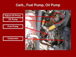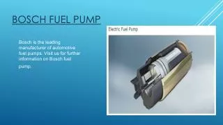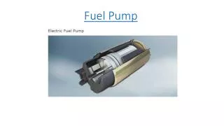

Fuel pump
E N D
Presentation Transcript
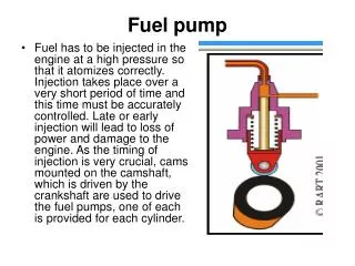
Fuel pump • Fuel has to be injected in the engine at a high pressure so that it atomizes correctly. Injection takes place over a very short period of time and this time must be accurately controlled. Late or early injection will lead to loss of power and damage to the engine. As the timing of injection is very crucial, cams mounted on the camshaft, which is driven by the crankshaft are used to drive the fuel pumps, one of each is provided for each cylinder.
As the cam rotates, it operates a spring loaded ram (plunger), which moves up and down in a cylinder (barrel). As the plunger moves up the barrel, the pressure of fuel above the plunger rises very quickly. The high pressure fuel then opens fuel valve (injector) and is sprayed into the cylinder as tiny droplets known as atomization. It is important to notice that injection takes place only when the plunger is moving up the cam slope.
In the first, the plunger has a helix machined into it, which also has a vertical grove and an annular groove at the base of the helix. The plunger reciprocates in a barrel, located in a pump body, which has a spill ports, connected to the suction side of the pump, drilled so that they are above the top of the plunger, when the cam follower is on the base circle of the cam. The plunger is keyed to a sleeve which has a gearwheel (pinion) machined into it. The pinion meshes with a rack, which can rotate the plunger relative to the barrel. The rack is connected the engine speed governor.
As the plunger moves upwards in the barrel, injection will commence once the plunger has closed off the spill ports and the pressure builds up. As soon as helix or scroll passes the spill ports, the pressure above the plunger will drop immediately, even though the plunger is still moving upwards. It should therefore be evident that the amount of fuel injected into the cylinder is dependent upon the position of helix relative to the spill port. When the vertical groove is lined up with the spill port, then no fuel injection will take place and the engine will stop. In some fuel pumps, there are two helices and two no load grooves diametrically opposite to each other. This gives a balanced plunger.
The plunger and barrel are machined to very fine tolerances. Wear due to abrasive particles in the fuel will mean that the pump will take longer to build up the injection pressure required. Wear due to erosion also takes place on the top edge of the plunger and the edge of helix and spill ports. This together with the wear in barrel and plunger, will lead to the injection timing becoming retarded, for which adjustments have to be made. On the scroll or helix type of pump described above, the start of injection (when top of the plunger covers the spill port) is fixed and the end of injection is variable and engine load dependent.
Fuels of different qualities may require advancing or retarding the injection timing. Also if the fuel injection timings are advanced when the engine is running at loads below maximum continuous rating (MCR), than a saving in fuel can be achieved. This method of varying the injection timing is known as Variable Injection Timing (VIT).
This method may be achieved by having coarse threads cut into the bottom of the barrel and locating it in a threaded sleeve, which is turned by a rack and pinion. The barrel is free to move up and down in the pump casing but cannot rotate. This means that as the threaded sleeve is rotated by VIT rack, the position of the spill port relative to the plunger is changed, thus altering the beginning of injection.
The second method of altering the quantity of fuel is by operating a suction and spill valves operated by push rods. A plain plunger reciprocates in a barrel. As the plunger moves up and down, two pivoted levers operate push rods, which open and close the suction and spill valves. When the cam follower is on the base circle of the cam, then the suction valve is open and spill valve is closed. As the plunger moves up the barrel, the suction valve push rod moves downwards and the suction valve closes.
Injection then commences and fuel is delivered to the fuel injector via a non return valve. As the plunger continues moving upwards, the spill valve push rod moves upwards and opens the spill valve, the pressure above the plunger falls and the injection of ceases. The quantity of fuel delivered can be controlled by altering the position of eccentric pivot for the spill valve operating lever. This will cause the valve to open earlier or later. By altering the position of suction valve pivot, the start of the injection can similarly be controlled. This pump thus utilizes VIT. This pump will not suffer from erosion problems that effect the scroll type of pump. However, wear due abrasive particles in the fuel will still affect the performance. Regular maintenance will include overhaul of valves and their seats.
Fuel pump of B&W MAN engines • The pump is basically a jerk type with plunger moving in a matched barrel, using two helical grooves machined in the plunger to control the end of injection by uncovering the spill ports and causing the discharge pressure to drop rapidly, thus causing the needle valve in the injector to close. Oil is supplied to the barrel via the spill ports and a suction valve.
The suction valve, situated on top of the barrel, opens when the pressure in the barrel falls below the pressure of the supply pump pressure i.e. on the downward stroke of the plunger, while spill ports are covered by the plunger. Replaceable erosion plugs are fitted in the pump housing opposite the spill ports. The high pressure oil, spilling back, as the edge of helix uncovers the spill ports at the end of injection, hits the plugs, which prevent damage to the pump casing.
A puncture valve is fitted in top cover of the pump. It is opened when compressed air from the control air system acts on top of a piston fitted in the top cover. Fuel oil from the discharge side is returned back to the suction side of the pump and no fuel injection takes place. The puncture valve is operated in the following circumstances: • actuation of shut down system of all units • during air start sequence • when excessive leakage is detected from the double skinned fuel pipes.
Fuel oil leakage past the plunger to the cam case is prevented by the use of an “umbrella” seal. A spring loaded damper is fitted to the side of the pump connected to the suction side of the pump. This smoothes out the pressure fluctuations as the high pressure fuel spills back at the end of injection.
Variable Injection Timing (VIT) • As well as having the normal fuel quantity control (rack that rotates the plunger in barrel), the fuel pump is fitted with an adjustable barrel, which has large pitch threads machined at the bottom. The threaded barrel is located in a threaded sleeve, which is rotated by a second rack. As the sleeve cannot move axially and the barrel is prevented from rotating, then as the sleeve rotates, the barrel moves up and down. This alters the position of spill ports relative to the plunger and varying the start of the injection.
Reason for using VIT • The reason for using VIT is to achieve fuel economy. This achieved by advancing the injection timing so that maximum combustion pressure (pmax) is achieved at about 85% MCR. The system is set up so that there is no change in injection timings at low loads (upto 40% MCR). This is to avoid frequent changes of pump lead during maneuvering.
As the engine load increases above 40% MCR, the start of injection advances. When the engine reaches 85% MCR, at which engine is designed to have reached maximum pmax, the servos retard the fuel injection timing so that the maximum combustion pressure is kept constant between 85% and 100% MCR.
How VIT is achieved • Low pressure air is fed to the pressure control valve, the output of which fed to the VIT servos on the fuel pump. A link from the governor output or fuel pump control handwheel, moves a pivoted bar, the position of which controls the output pressure of the pressure control valve.
The position of the control valve is adjustable, which can be used to allow for fuels of varying qualities and changes in the camshaft timing due to chain elongation. The pivots are also adjustable for setting up of the VIT and adjustments of the breakpoint position.