Download
1 / 31
310 likes | 478 Views
Theory and Practice of Electron Microprobe Analysis Geoc 575 Nelia Dunbar Bureau Office B-101 x5783 office x5155 lab. Electron Microprobe analysis and Scanning Electron microscopy Electron microprobe analysis (EMPA) Analytical technique in which a beam of electrons is

E N D
Theory and Practice of Electron Microprobe Analysis Geoc 575 Nelia Dunbar Bureau Office B-101 x5783 office x5155 lab
Electron Microprobe analysis and Scanning Electron microscopy • Electron microprobe analysis (EMPA) • Analytical technique in which a beam of electrons is • focused on a sample surface, producing X-rays from the material in the sample. Used for chemical mapping of a sample surface, and also for quantitative chemical analysis.
What is EMPA used for? -Quantitative or qualitative chemical analysis of a very small focussed spot (<1um) on a polished sample surface. A non-destructive technique. Useful for: -Mineral identification -Descriptive petrology -Geothermometry and geobarometry -Experimental petrology -Cosmochemistry -Zoning in minerals -Diffusion studies -Particle analysis
-Chemical mapping of a polished sample surface. Accomplished by sweeping (rastering) the beam over the sample surface. Used for many of the same types of studies described above. Particularly useful for: • -Location and distribution of phases • -Quick location and identification of trace particles • -Subtle zoning patterns in mineral samples • -Examination of the interfaces between phases What is EMPA used for? (con’t)
Secondary electron imaging (SEI, also commonly SEM) • A related technique in which a very finely-focussed beam of electrons is swept across a sample surface, producing secondary electrons which are then detected by a scintillation detector. This technique is used for high-magnification and resolution imaging of a 3-D sample surface.
What is secondary electron imaging used for? • -Morphological imaging of a rough sample surface. Also accomplished by rastering the beam over the sample surface, but does only yields morphological, not chemical, information. Useful for: • -Determining the morphology and morphological relationship between mineral phases that can be difficult to detect with the petrographic microscope • -Determining size of very small mineral phases
The instrumentation which allows these two types of analyses is closely related, in that the electron optics system is very similar. The CAMECA SX-100 instrument is primarily an electron microprobe designed for quantitative chemical analysis, but also can also be used for secondary electron imaging.
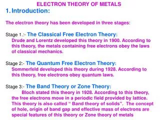
History of Electron Probe Microanalysis • X-RAYS • 1895- Roentgen discovers X-rays • X-rays are high-frequency electromagnetic radiation with energy intermediate between far-UV and gamma ray regions. This leads to development in numerous fields, particularly medical. • 1911- Barkla recognized characteristic radiation • This scientist recognizes that x-rays emitted from different elements produce x-rays of different energy and wavelength.
1913-1914- Moseley quantifies the relationship between atomic number and x-ray wavelength. • Moseley photographed and studied characteristic x-ray radiation. He determined that the atomic number of an atom is more important than the atomic weight in determining the characteristics of x-rays generated from that element. Formulated Moseley's law: • λ α 1/Z2 • where λ = x-ray wavelength • Z = atomic number • 1912- Von Laua. Diffraction • Von Laua and coworkers speculated that wavelength of x-rays and crystal lattice parameters are similar, so x-rays could be diffracted by crystals.
1914- Bragg. Developed Bragg's Law • Bragg's law defines a diffraction relationship between the wavelength of an incoming ray and the d-spacing of a diffracting crystal. • Bragg's Law: • n λ = 2d sinθ • where n = the order of reflection • λ = wavelength of incident ray • d = interplanar spacing of the crystal • θ = angle of incidence and reflection of incident ray • This is the principle under which the wavelength-dispersive detectors operate.
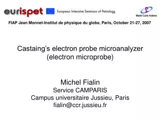
1951 R. Castaing. Developed the first electron microprobe • Castaing was a doctoral student at the University of Paris. His doctoral thesis was titled: "Application of electron beams to a method of local chemical and crystallographic analysis". He is the originator of the electron microprobe as we know it today.
-Characteristic X-rays • Produced by electronic transitions within inner electron shells. Can be explained by examining the Rutherford-Bohr model of the atom, in which electrons orbit in a number of shells around a nucleus. • -Backscattered electrons • Primary electrons from the beam that undergo violent collisions with atoms in the sample and are scattered back from the sample surface. The proportion of backscattered electrons is directly proportional to the mean atomic number of the sample. Backscatter from C is 8%, from U is 50%. Modern BSE detectors can detect mean Z differences of between 0.1 and 0.3 Z. • -Secondary electrons • Secondary electrons are produced by ionization of atoms in the sample by interaction with the primary beam. Secondary electrons have low energies, and cannot escape from deep within the sample. Therefore, this electron signal produces the highest-resolution morphological images of a sample surface.
-Cathodoluminescence • Visible light emitted by minerals bombarded by electrons. Mechanism depends on the mineral in question. This property of certain minerals, particularly diamond and some types of feldspar, allow the beam to be viewed optically which is useful for focussing. • -Continuous X-rays • Most interactions between the primary beam do not produce the characteristic x-rays discussed earlier. Many electrons from the incident beam are simply decelerated by the interactions with outer orbital shell electrons from atoms within the sample. The energy released during these decelerations produces a continuous (or bremsstrahlung) x-ray spectrum. These x-rays are noise, and are undesirable, but unavoidable. • -Auger Electrons • When an atom is ionized in an inner shell, energy may be released by ejecting another bound electron, instead of producing an x-ray. These electrons can have characteristic energy. Most effective for low atomic number elements (<10).
-Characteristic X-rays • Produced by electronic transitions within inner electron shells. Can be explained by examining the Rutherford-Bohr model of the atom, in which electrons orbit in a number of shells around a nucleus. From Reed, 1996
-Backscattered electrons • Primary electrons from the beam that undergo violent collisions with atoms in the sample and are scattered back from the sample surface. The proportion of backscattered electrons is directly proportional to the mean atomic number of the sample. Backscatter from C is 8%, from U is 50%. Modern BSE detectors can detect mean Z differences of between 0.1 and 0.3 Z.
-Secondary electrons • Secondary electrons are produced by ionization of atoms in the sample by interaction with the primary beam. Secondary electrons have low energies, and cannot escape from deep within the sample. Therefore, this electron signal produces the highest-resolution morphological images of a sample surface.
Electron interaction volumes Effect of beam interaction (damage) in plastic (polymethylmethacrylate), from Everhart et al., 1972. All specimens received same beam dosage, but were etched for progressively longer times, showing in (a) strongest electron energies, to (g) the region of least energetic electrons. Note teardrop shape in (g) From J. Fournelle http://www.geology.wisc.edu/~johnf/g777/
Major components of an electron microprobe • 1. Electron optic system. • -Electron gun • -focussing lenses and apertures • -associated electronics • 2. Optical microscope and sample stage • -optical/video apparatus for viewing sample • -high-precision stage that holds samples and standards • 3. X-ray optic system • -spectrometers • -secondary electron detector • -backscatter electron detector • -flow-proportional gas counters
Major components of an electron microprobe • 4. Vacuum system • -roughing pumps • -diffusion pump • -ion pump • 5. Amplification/electronics • -amplification of signals • 6. Computer Controller • -interface between instrument and operator • -image collection and processing systems • -quantitative data reduction programs