Download
1 / 33
410 likes | 770 Views
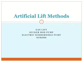
Introduction to Artificial Lift Methods. This section introduces the main methods of artificial lift with a brief description, advantages, disadvantages, operational windows considering depth vs. rate. All methods are covered in detail in following sections.

E N D
Introduction to Artificial Lift Methods • This section introduces the main methods of artificial lift with a brief description, advantages, disadvantages, operational windows considering depth vs. rate. • All methods are covered in detail in following sections.
Overview of Artificial Lift Systems: Features Advantages Disadvantages
Sucker Rod Tubing Anchor/ Catcher Sucker Rod Pump Assembly Reciprocating Rod LiftSystem Advantages High System Efficiency Optimization Controls Available Economical to Repair and Service Positive Displacement/Strong Drawdown Upgraded Materials Reduce Corrosion Concerns Flexibility - Adjust Production Through Stroke Length and Speed High Salvage Value for Surface & Downhole Equipment
Sucker Rod Tubing Anchor/ Catcher Sucker Rod Pump Assembly Reciprocating Rod LiftSystem Limitations Potential for Tubing and Rod Wear Gas-Oil Ratios Most Systems Limited to Ability of Rods to Handle Loads - Volume Decreases As Depth Increases Environmental and Aesthetic Concerns
Typical Range Maximum* OperatingDepth100 - 11,000’ TVD16,000’ TVD OperatingVolume5 - 1500 BPD 5000 BPD OperatingTemperature100° - 350° F 550° F Wellbore0 - 20° Landed 0 - 90° LandedDeviationPump Pump - <15°/100’ Build Angle Corrosion Handling Good to Excellent w/ Upgraded Materials Gas Handling Fair to Good Solids Handling Fair to Good Fluid Gravity >8° API Servicing Workover or Pulling Rig Prime Mover Type Gas or Electric Offshore Application Limited System Efficiency 45%-60% Rod Lift System Application Considerations Sucker Rod Tubing Anchor/ Catcher Sucker Rod Pump Assembly *Special Analysis Required
Vertical Electric Wellhead Drive Casing Production Tubing Sucker Rod Sucker Rod Coupling Tubing Collar Stator Rotor Tubing Collar Tag Bar Sub Progressing Cavity Pumping System Advantages Low Capital Cost Low Surface Profile for Visual and Height Sensitive Areas High System Efficiency Simple Installation, Quiet Operation Pumps Oils and Waters with Solids Low Power Consumption Portable Surface Equipment Low Maintenance Costs Use In Horizontal/Directional Wells
Vertical Electric Wellhead Drive Casing Production Tubing Sucker Rod Sucker Rod Coupling Tubing Collar Stator Rotor Tubing Collar Tag Bar Sub Progressing Cavity Pumping System Limitations Limited Depth Capability Temperature Sensitivity to Produced Fluids Low Volumetric Efficiencies in High-Gas Environments Potential for Tubing and Rod Coupling Wear Requires Constant Fluid Level above Pump
Typical Range Maximum* OperatingDepth2,000 --4,500’ TVD6,000’ TVD OperatingVolume5 -2,200 BPD 4,500 BPD OperatingTemperature75 -150° F 250° F WellboreN/A 0 - 90° LandedDeviationPump - <15°/100’ Build Angle Corrosion Handling Fair Gas HandlingGood Solids HandlingExcellent Fluid Gravity<35° API Servicing Workover or Pulling Rig Prime Mover Type Gas or Electric Offshore Application Good (ES/PCP) System Efficiency40%-70% Vertical Electric Wellhead Drive Casing Production Tubing Sucker Rod Sucker Rod Coupling Tubing Collar Stator Rotor *Special Analysis Required Tubing Collar Tag Bar Sub Progressing Cavity System Application Considerations
Injection Gas In Produced Hydrocarbons Out Side Pocket Mandrel with Gas Lift Valve Side Pocket Mandrel with Gas Lift Valve Side Pocket Mandrel with Gas Lift Valve Completion Fluid Single Production Packer Gas LiftSystem Advantages High Degree of Flexibility and Design Rates Wireline Retrievable Handles Sandy Conditions Well Allows For Full Bore Tubing Drift Surface Wellhead Equipment Requires Minimal Space Multi-Well Production From Single Compressor Multiple or Slimhole Completion
Injection Gas In Produced Hydrocarbons Out Side Pocket Mandrel with Gas Lift Valve Side Pocket Mandrel with Gas Lift Valve Side Pocket Mandrel with Gas Lift Valve Completion Fluid Single Production Packer Gas LiftSystem Limitations Needs High-Pressure Gas Well or Compressor One Well Leases May Be Uneconomical Fluid Viscosity Bottomhole Pressure High Back-Pressure
Typical Range Maximum* OperatingDepth5,000 -10,000’ TVD15,000’ TVD OperatingVolume100 - 10,000 BPD 30,000 BPD OperatingTemperature100 - 250° F 400° F Wellbore0- 50° 70°Deviation Short to Medium Radius Corrosion HandlingGood to Excellent withUpgraded Materials Gas HandlingExcellent Solids HandlingGood Fluid Gravity Best in >15° API Servicing Wireline or Workover Rig Prime Mover TypeCompressor Offshore ApplicationExcellent System Efficiency10% - 30% Injection Gas In Produced Hydrocarbons Out Side Pocket Mandrel with Gas Lift Valve Side Pocket Mandrel with Gas Lift Valve Side Pocket Mandrel with Gas Lift Valve Completion Fluid Single Production Packer *Special Analysis Required Gas Lift System Application Considerations
Lubricator Catcher Solar Panel Orifice Control Valves Controller Motor Valve Dual “T” Pad Plunger Bumper Spring Plunger LiftSystem Advantages Requires No Outside Energy Source - Uses Well’s Energy to Lift Dewatering Gas Wells Rig Not Required for Installation Easy Maintenance Keeps Well Cleaned of Paraffin Deposits Low Cost Artificial Lift Method Handles Gassy Wells Good in Deviated Wells Can Produce Well to Depletion
Lubricator Catcher Solar Panel Orifice Control Valves Controller Motor Valve Dual “T” Pad Plunger Bumper Spring Plunger LiftSystem Limitations Specific GLR’s to Drive System Low Volume Potential (200 BPD) Solids Requires Surveillance to Optimize
Typical Range Maximum* OperatingDepth8,000’ TVD19,000’ TVD OperatingVolume1-5 BPD 200 BPD OperatingTemperature120° F 500° F Wellbore N/A 80°Deviation Corrosion Handling Excellent Gas HandlingExcellent Solids HandlingPoor to Fair GLR Required300 SCF/BBL/1000’ Depth Servicing Wellhead Catcher or Wireline Prime MoverTypeWell’s Natural Energy Offshore ApplicationN/A at this time System Efficiency N/A Lubricator Catcher Solar Panel Orifice Control Valves Controller Motor Valve Dual “T” Pad Plunger Bumper Spring *Special Analysis Required Plunger Lift System Application Considerations
Surface Power Fluid Package Production Casing High Pressure Power Fluid Packer Nose Bottom Hole Assembly Piston or Jet “Free Pump” Standing Valve Hydraulic Piston Lift System Advantages Often “Free” or Wireline Retrievable Positive Displacement - Strong Drawdown Double-Acting High-Volumetric Efficiency Good Depth/Volume Capability - +15,000 ft. Deviated Wells Multi-Well Production From Single Surface Package Horsepower Efficiency
Surface Power Fluid Package Production Casing High Pressure Power Fluid Packer Nose Bottom Hole Assembly Piston or Jet “Free Pump” Standing Valve Hydraulic Piston Lift System Limitations Solids Requires Specific Bottom Hole Assemblies Medium Volume Potential (50 - 1000 BPD) Require Service Facilities Free Gas Requires High-Pressure Surface Line
Typical Range Maximum* OperatingDepth7,500 - 10,000’ TVD17,000’ TVD OperatingVolume50 - 500 BPD 4,000 BPD OperatingTemperature100° - 250° F 500° F Wellbore0 - 20° 0 - 90° Pump DeviationLanded Pump Placement -<15°/100’ Build Angle Corrosion Handling Good Gas HandlingFair Solids HandlingPoor Fluid Gravity>8° API Servicing Hydraulic or Wireline Prime Mover TypeMulti-Cylinder or Electric Offshore Application Good System Efficiency 40%-50% Surface Power Fluid Package Production Casing High Pressure Power Fluid Packer Nose Bottom Hole Assembly Piston or Jet “Free Pump” Standing Valve Hydraulic Piston Lift Application Considerations *Special Analysis Required
Surface Power Fluid Package Production Casing High Pressure Power Fluid Packer Nose Bottom Hole Assembly Piston or Jet “Free Pump” Standing Valve Hydraulic Jet Lift System Advantages No Moving Parts High Volume Capability “Free” Pump Deviated Wells Multi-Well Production from Single Surface Package Low Pump Maintenance
Surface Power Fluid Package Production Casing High Pressure Power Fluid Packer Nose Bottom Hole Assembly Piston or Jet “Free Pump” Standing Valve Hydraulic Jet Lift System Limitations Producing Rate Relative to Bottomhole Pressure Some Require Specific Bottomhole Assemblies Lower Horsepower Efficiency High-Pressure Surface Line Requirements
Typical Range Maximum* OperatingDepth5,000 - 10,000’ TVD15,000’ TVD OperatingVolume300 - 1,000 BPD >15,000 BPD OperatingTemperature100° - 250° F 500° F Wellbore0 - 20° 0 - 90° Pump DeviationHole Angle Placement - <24°/100’ Build Angle Corrosion Handling Excellent Gas HandlingGood Solids Handling Good Fluid Gravity>8° API Servicing Hydraulic or Wireline Prime Mover TypeMulti-Cylinder or Electric Offshore ApplicationExcellent System Efficiency 10%-30% Surface Power Fluid Package Production Casing High Pressure Power Fluid Packer Nose Bottom Hole Assembly Piston or Jet “Free Pump” Standing Valve Hydraulic Jet Lift Application Considerations *Special Analysis Required
Motor Control Vent Box Produced Hydrocarbons Out Production Tubing Pump Flat CableExtension Seal Section Motor Electric SubmersiblePumping SystemAdvantages High Volume and Depth Capability High Efficiency Over 1,000 BPD Low Maintenance Minor Surface Equipment Needs Good in Deviated Wells Adaptable to All Wells With 4-1/2” Casing and Larger Use for Well Testing
Motor Control Vent Box Produced Hydrocarbons Out Production Tubing Pump Flat CableExtension Seal Section Motor Electric SubmersiblePumping SystemLimitations Available Electric Power Limited Adaptability to Major Changes in Reservoir Difficult to Repair In the Field Free Gas and/or Abrasives High Viscosity Higher Pulling Costs
Typical Range Maximum* OperatingDepth1,000’ -10,000’ TVD 15,000’ TVD OperatingVolume200 - 20,000 BPD 30,000 BPD OperatingTemperature100° - 275° F 400° F Wellbore10° 0 - 90° Pump DeviationPlacement - <10° Build Angle Corrosion HandlingGood Gas HandlingPoor to Fair Solids HandlingPoor to Fair Fluid Gravity >10° API ServicingWorkover or Pulling Rig Prime Mover Type Electric Motor Offshore Application Excellent System Efficiency 35%-60% Electric Submersible Systems Application Considerations Motor Control Vent Box Produced Hydrocarbons Out Production Tubing Pump Flat CableExtension Seal Section Motor *Special Analysis Required
2. Elimination Process Progressing Cavity PlungerLift HydraulicPiston HydraulicJet Rod Lift Gas Lift Electric Submersible OperatingDepth OperatingVolume (Typical) OperatingTemperature CorrosionHandling GasHandling SolidsHandling FluidGravity Servicing Prime Mover OffshoreApplication Overall SystemEfficiency 100’ -16,000’ TVD 1,000’-15,000’ TVD 2,000’ -6,000’ TVD 5,000’ -15,000’ TVD 8,000’ - 19,000’ TVD 7,500’ -17,000’ TVD 5,000’ - 15,000’ TVD 5 - 5000BPD 50 - 4,000 BPD 200 - 30,000 BPD 5 - 4,500 BPD 200 - 30,000 BPD 300 - >15,000 BPD 1 - 5 BPD 100° -550° F 100° - 400° F 100° -500° F 100° -500° F 100° -400° F 120° - 500º F 75°-250° F Good toExcellent Good toExcellent Fair Good Excellent Good Excellent Fair toGood Poor to Fair Excellent Good Excellent Fair Good Fair toGood Poor toFair Poor to Fair Excellent Good Poor Good GLR Required -300 SCF/BBL/1000’ Depth >8° API <35° API >8° API >8° API >15° API >10° API WellheadCatcher or Wireline Workover orPulling Rig Workover orPulling Rig Wireline orWorkover Rig Hydraulic orWireline Hydraulic orWireline Workover orPulling Rig Gas or Electric ElectricMotor Gas or Electric Wells’ Natural Energy Multicylinderor Electric Multicylinderor Electric Compressor N/A Limited Good Excellent Good Excellent Excellent 45% - 55% 10% - 30% 35% - 60% 10% - 30% N/A 45% - 60% 40% - 70%
35,000 30,000 Gas Lift ESP 2. Elimination Process 25,000 20,000 15,000 Hydraulic Jet Pump 10,000 5,000 1,000 2,000 3,000 4,000 5,000 6,000 7,000 8,000 9,000 10,000 11,000 12,000 13,000 14,000 15,000 16,000 High Volume Hydraulic Jet Pumps, Electric Submersible Pumping and Gas Lift Barrels per Day Lift Depth
4,500 4,000 3,500 2. Elimination Process 3,000 2,500 2,000 Recip. Hydraulic 1,500 Recip. Rod Pump 1,000 PC Pumps 500 Plunger Lift 11,000 14,000 16,000 2,000 7,000 10,000 1,000 3,000 13,000 15,000 12,000 5,000 9,000 4,000 6,000 8,000 Lower Volume Reciprocating Hydraulic Pumps, PC Pumps, Rod Pumps & Plunger Lift Barrels per Day Lift Depth
Summary • Information has been presented on the major methods of AL. • Already enough information has been presented that would allow you to rule out certain methods of lift for particular applications. • Later sections describe the various systems in detail, discuss operational considerations, discuss design and analysis and other details of each system.