Understanding Linear Amplification in Analog Systems: Key Concepts and Applications
400 likes | 543 Views
This chapter focuses on the essential concepts of linear amplification in analog systems, including voltage, current, and power gains, and their decibel representation. It delves into input/output resistances, transfer functions, and Bode plots to characterize amplifiers. Key amplifier types such as low-pass, high-pass, band-pass, and band-reject are explored alongside biasing techniques for linear amplification and distortion effects. The chapter also discusses two-port representations using g-, h-, y-, and z-parameters, offering practical insights for applications like FM stereo receivers.

Understanding Linear Amplification in Analog Systems: Key Concepts and Applications
E N D
Presentation Transcript
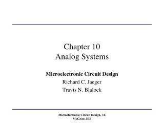
Chapter 10Analog Systems Microelectronic Circuit Design Richard C. Jaeger Travis N. Blalock Microelectronic Circuit Design McGraw-Hill Chap10 - 1
Chapter Goals • Develop understanding of linear amplification concepts such as: • Voltage gain, current gain, and power gain, • Gain conversion to decibel representation, • Input and output resistances, • Transfer functions and Bode plots, • Cutoff frequencies and bandwidth, • Low-pass, high-pass, band-pass, and band-reject amplifiers, • Biasing for linear amplification, • Distortion in amplifiers, • Two-port representations of amplifiers, • g-, h-, y-, and z-parameters, • Use of transfer function analysis in SPICE. Microelectronic Circuit Design McGraw-Hill Chap10 - 2
Example of Analog Electronic System: FM Stereo Receiver • Linear functions: Radio and audio frequency amplification, frequency selection (tuning), impedance matching(75-W input, tailoring audio frequency response, local oscillator • Nonlinear functions: DC power supply(rectification), frequency conversion (mixing), detection/demodulation Microelectronic Circuit Design McGraw-Hill Chap10 - 3
Amplification: Introduction A complex periodic signal can be represented as the sum of many individual sine waves. We consider only one component with amplitude VS =1 mV and frequency wS with 0 phase (signal is used as reference): Amplifier output is sinusoidal with same frequency but different amplitude VO and phase θ: Microelectronic Circuit Design McGraw-Hill Chap10 - 4
Amplification: Introduction (contd.) Amplifier output power is: Here, PO = 100 W and RL=8 W Output power also requires output current which is: Input current is given by phase is zero because circuit is purely resistive. Microelectronic Circuit Design McGraw-Hill Chap10 - 5
Amplification: Gain • Voltage Gain: Magnitude and phase of voltage gain are given by and For our example, • Current Gain: Magnitude of current gain is given by Microelectronic Circuit Design McGraw-Hill Chap10 - 6
Amplification: Gain (contd.) • Power Gain: For our example, On decibel scale, i.e. in dB Microelectronic Circuit Design McGraw-Hill Chap10 - 7
Amplifier Biasing for Linear Operation VI = dc value of vI, vi = time-varying component For linear amplification- vI must be biased in desired region of output characteristic by VI. If slope of output characteristic is positive, input and output are in phase (amplifier is non-inverting). If slope of output characteristic is negative, input and output signals are 1800 out of phase (amplifier is inverting). Microelectronic Circuit Design McGraw-Hill Chap10 - 8
Amplifier Biasing for Linear Operation (contd.) Voltage gain depends on bias point. Eg: if amplifier is biased at VI = 0.5 V, voltage gain will be +40 for input signals satisfying If input exceeds this value, output is distorted due to change in amplifier slope. Microelectronic Circuit Design McGraw-Hill Chap10 - 9
Amplifier Biasing for Linear Operation (contd.) Output signals for 1 kHZ sinusoidal input signal of amplitude 50 mV biased at VI= 0.3 V and 0.5V: For VI =0.3V: Gain is 20, output varies about dc level of 4 V. For VI =0.5V: Gain is 40, output varies about dc level of 10 V. Microelectronic Circuit Design McGraw-Hill Chap10 - 10
Distortion in Amplifiers • Different gains for positive and negative values of input cause distortion in output. • Total Harmonic Distortion (THD) is a measure of signal distortion that compares undesired harmonic content of a signal to the desired component. Microelectronic Circuit Design McGraw-Hill Chap10 - 11
Total Harmonic Distortion dc desired output 2nd harmonic distortion 3rd harmonic distortion Numerator= sum of rms amplitudes of distortion terms, Denominator= desired component Microelectronic Circuit Design McGraw-Hill Chap10 - 12
Two-port Models for Amplifiers • Simplifies amplifier-behavior modeling in complex systems. • Two-port models are linear network models, valid only under small-signal conditions. • Represented by g-, h-, y- and z-parameters. • (v1, i1) and (v2, i2) represent signal components of voltages and currents at the network ports. Microelectronic Circuit Design McGraw-Hill Chap10 - 13
g-parameters Using open-circuit (i=0) and short-circuit (v=0) termination conditions, Open-circuit input conductance Reverse short-circuit current gain Forward open-circuit voltage gain Short-circuit output resistance Microelectronic Circuit Design McGraw-Hill Chap10 - 14
g-parameters:Example Problem:Find g-parameters. Approach: Apply specified boundary conditions for each g-parameter, use circuit analysis. For g11 and g21: apply voltage v1 to input port and open circuit output port. For g12 and g22: apply current i2 to output port and short circuit input port. Microelectronic Circuit Design McGraw-Hill Chap10 - 15
Hybrid or h-parameters Using open-circuit (i=0) and short-circuit (v=0) termination conditions, Short-circuit input resistance Reverse open-circuit voltage gain Forward short-circuit current gain Open-circuit output conductance Microelectronic Circuit Design McGraw-Hill Chap10 - 16
h-parameters:Example Problem:Find h-parameters for the same network (used in g-parameters example). Approach: Apply specified boundary conditions for each h-parameter, use circuit analysis. For h11 and h21: apply current i1 to input port and short circuit output port. For h12 and h22: apply voltage v2 to output port and open circuit input port. Microelectronic Circuit Design McGraw-Hill Chap10 - 17
Admittance or y-parameters Using open-circuit (i=0) and short-circuit (v=0) termination conditions, Short-circuit input conductance Reverse short-circuit transconductance Forward short-circuit transconductance Short-circuit output conductance Microelectronic Circuit Design McGraw-Hill Chap10 - 18
y-parameters:Example Problem:Find y-parameters for the same network (used in g-parameters example). Approach: Apply specified boundary conditions for each y-parameter, use circuit analysis. For y11 and y21: apply voltage v1 to input port and short circuit output port. For y12 and y22: apply voltage v2 to output port and short circuit input port. Microelectronic Circuit Design McGraw-Hill Chap10 - 19
Impedance or z-parameters Using open-circuit (i=0) and short-circuit (v=0) termination conditions, Open-circuit input resistance Reverse open-circuit transresistance Forward open-circuit transresistance Open-circuit output resistance Microelectronic Circuit Design McGraw-Hill Chap10 - 20
z-parameters:Example Problem:Find z-parameters for the same network (used in g-parameters example). Approach: Apply specified boundary conditions for each z-parameter, use circuit analysis. For z11 and z21: apply current i1 to input port and open circuit output port. For z12 and z22: apply current i2to output port and open circuit input port. Microelectronic Circuit Design McGraw-Hill Chap10 - 21
Mismatched Source and Load Resistances: Voltage Amplifier g-parameter representation (g12=0) with Thevenin equivalent of input source: If Rin >> Rs and Rout<< RL, In an ideal voltage amplifier, and Rout=0 Microelectronic Circuit Design McGraw-Hill Chap10 - 22
Mismatched Source and Load Resistances: Current Amplifier h-parameter representation (h12=0) with Norton equivalent of input source: If Rs >> Rin and Rout>> RL, In an ideal current amplifier, and Rin=0 Microelectronic Circuit Design McGraw-Hill Chap10 - 23
Amplifier Transfer Functions Av(s)=Frequency-dependent voltage gain Vo(s) and Vs(s) = Laplace Transforms of input and output voltages of amplifier, (In factorized form) (-z1, -z2,…-zm)=zeros (frequencies for which transfer function is zero) (-p1, -p2,…-pm)=poles (frequencies for which transfer function is infinite) (In polar form) Bode plots display magnitude of the transfer function in dB and the phase in degrees (or radians) on a logarithmic frequency scale.. Microelectronic Circuit Design McGraw-Hill Chap10 - 24
Low-pass Amplifier: Description • Amplifies signals over a range of frequencies including dc. • Most operational amplifiers are designed as low pass amplifiers. • Simplest (single-pole) low-pass amplifier is described by Ao = low-frequency gain or mid-band gain wH = upper cutoff frequency or upper half-power point of amplifier. Microelectronic Circuit Design McGraw-Hill Chap10 - 25
Low-pass Amplifier: Magnitude Response For w<<wH : For w>>wH : For w=wH : • Gain is unity (0 dB) atw=AowH , called gain-bandwidth product • Bandwidth (frequency range with constant amplification )= wH (rad/s) Microelectronic Circuit Design McGraw-Hill Chap10 - 26
Low-pass Amplifier: Phase Response If Ao positive: phase angle = 00 If Ao negative: phase angle = 1800 At wC: phase =450 One decade below wC: phase =5.70 One decade above wC: phase =84.30 Two decades below wC: phase =00 Two decades above wC: phase =900 Microelectronic Circuit Design McGraw-Hill Chap10 - 27
RC Low-pass Filter Problem: Find voltage transfer function Approach: Impedance of the where capacitor is 1/sC, use voltage division Microelectronic Circuit Design McGraw-Hill Chap10 - 28
High-pass Amplifier: Description • True high-pass characteristic impossible to obtain as it requires infinite bandwidth. • Combines a single pole with a zero at origin. • Simplest high-pass amplifier is described by wH = lower cutoff frequency or lower half-power point of amplifier. Microelectronic Circuit Design McGraw-Hill Chap10 - 29
High-pass Amplifier: Magnitude and Phase Response For w>>wL : For w<<wL : For w=wL : • Bandwidth(frequency range with constant amplification ) is infinite • Phase response is given by Microelectronic Circuit Design McGraw-Hill Chap10 - 30
RC High-pass Filter Problem: Find voltage transfer function Approach: Impedance of the where capacitor is 1/sC, use voltage division Microelectronic Circuit Design McGraw-Hill Chap10 - 31
Band-pass Amplifier: Description • Band-pass characteristic obtained by combining highpass and low-pass characteristics. • Transfer function of a band-pass amplifier is given by • Ac-coupled amplifier has a band-pass characteristic: • Capacitors added to circuit cause low frequency roll-off • Inherent frequency limitations of solid-state devices cause high-frequency roll-off. Microelectronic Circuit Design McGraw-Hill Chap10 - 32
Band-pass Amplifier: Magnitude and Phase Response • The frequency response shows a wide band of operation. • Mid-band range of frequencies given by , where Microelectronic Circuit Design McGraw-Hill Chap10 - 33
Band-pass Amplifier: Magnitude and Phase Response (contd.) At both wHand wL, assumingwL<<wH, Bandwidth =wH - wL. The phase response is given by Microelectronic Circuit Design McGraw-Hill Chap10 - 34
Narrow-band or High-Q Band-pass Amplifiers • Gain maximum at center frequency wo and decreases rapidly by 3 dB at wHand wL. • Bandwidth defined aswH - wL, is a small fraction ofwowith width determined by: • For high Q, poles will be complex and • Phase response is given by: Microelectronic Circuit Design McGraw-Hill Chap10 - 35
Band-Rejection Amplifier or Notch Filter • Gain maximum at frequencies far from wo and exhibits a sharp null at wo. • To achieve sharp null, transfer function has a pair of zeros on jw axis at notch frequency wo , and poles are complex. • Phase response is given by: Microelectronic Circuit Design McGraw-Hill Chap10 - 36
All-pass Function • Uniform magnitude response at all frequencies. • Can be used to tailor phase characteristics of a signal • Transfer function is given by: • For positive Ao, Microelectronic Circuit Design McGraw-Hill Chap10 - 37
Complex Transfer Functions Amplifier has 2 frequency ranges with constant gain. Midband region is always defined as region of highest gain and cutoff frequencies are defined in terms of midband gain. Since wH = w4 and wL = w3, Microelectronic Circuit Design McGraw-Hill Chap10 - 38
Bandwidth Shrinkage • If critical frequencies aren’t widely spaced, the poles and zeros interact and cutoff frequency determination becomes complicated. • Example : for which , Av(0) = Ao Upper cutoff frequency is defined by or Solving for wH yields wH =0.644w1.The cutoff frequency of two-pole function is only 64% that of a single-pole function. This is known as bandwidth shrinkage. Microelectronic Circuit Design McGraw-Hill Chap10 - 39