Acoustic Beam Forming Array
Acoustic Beam Forming Array. By: Angelo Charbonnier. Project Introduction. Current Sonar Systems can be classified as either side scanning or bottom penetrating Side scanning systems sweep a large area below them to the sea bed.

Acoustic Beam Forming Array
E N D
Presentation Transcript
Acoustic Beam Forming Array By: Angelo Charbonnier
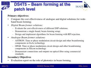
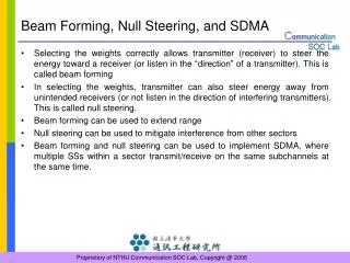
Project Introduction • Current Sonar Systems can be classified as either side scanning or bottom penetrating • Side scanning systems sweep a large area below them to the sea bed. • Bottom penetrating systems use a narrow more powerful beam to penetrate the sea bed. • Our system will use beam forming to combined the two systems so that a large area beneath the array can be swept with penetrating capabilities.
Current Tests • Test Data was created for simulation with beam forming techniques. • Testing of the array is being performed at a local lake and data is being obtained for analysis with beam forming.
Further Analysis • Power analysis is being performed so that the expected levels of acoustic power is being achieved based on our signal and input electrical power • Calibration of all 16 of the systems hydrophones needs to be complete so that all the input levels are correctly being measured. • Calibration is achieved through a direct comparison of a reference hydrophone’s recorded data to our own
Beam Forming • We record delayed sound waves from sixteen different hydrophones. • For each place the sound wave hits, a delayed signal comes back to each hydrophone with some delay • True signals have noise thus the delay is not easy to see Figure : Sample Signal with noise Figure :Sample delayed sound waves from 9 hydrophones
Beam FormingMethod • Each recording has a specific norm • Summing these signals creates a larger norm • By sampling the summations we generate a plot similar to the one shown • The peak is the correct delay because it has the max norm • We now know that the recorded object is located at -4 radians below the source