Download
1 / 26
300 likes | 503 Views
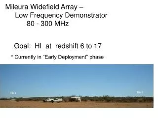
The Murchison Widefield Array: an SKA Precursor. Shep Doeleman - MIT Haystack For the MWA Project. A wide-field, low-frequency imaging array Optimized for wide FOV, high survey speed Frequency range 80-300 MHz: Sample RF Three key science goals Epoch of Reionization

E N D
The Murchison Widefield Array:an SKA Precursor Shep Doeleman - MIT Haystack For the MWA Project
A wide-field, low-frequency imaging array • Optimized for wide FOV, high survey speed • Frequency range 80-300 MHz: Sample RF • Three key science goals • Epoch of Reionization • Solar, Heliospheric and Ionospheric • Radio Transients • Designed to exploit RFI-quiet site in Western Australia What is the MWA?
The Partnership • Massachusetts Institute of Technology • Haystack Observatory (Project Office) • Kavli Institute • Harvard SAO • CSIRO (via synergy with ASKAP) • UMelbourne, Curtin, ANU (founding partners) • USydney, UTasmania, UWA, and others, ... • Raman Research Institute, India • Government of WA 3
Antenna tile (~4m diam.) clusters Array (~1.5km diam.) tile Cluster (50-100m diam.) node Coax out Tile beamformer Fiber out Central Processing Physical Layout
Tentative Configuration Aperture Plane UV Plane
A/D Coarse PFB Select 30.72MHz 20 Tflops 32 single pol 192 fibers over 1-3km 1024 sig No Fringe Stopping 80-300MHz 524,288 sig pairs 18 Tera CMACs 10kHz resolution 0.5 sec accumulate 160Gb/s 2-10 Tflop
Large N • Array configuration • Large data transport flow • Large multiplier for all processing • Correlator architecture • Calibration algorithms: real time • Cannot store raw data • Broad Science Case • Wide Field by design: transients • New analysis algorithms: EOR statistics • Links with solar, space weather community • Remote Site • International Project MWA as SKA Precursor
September 08 to March 09 • 32-tile system: as of yesterday 16 tiles fully functional (w/ bf and rx). • Progressive testing of production hardware systems • Milestone for funds release, June 09 • April 09 to December 09 • Buildout to ~256 tile system • In-depth testing, refinement of algorithms • January 2010 to June 2010 • Complete buildout to 512 tiles • Initiate key science investigations • 2010 - 2012 • Refinement and incremental expansion • 2013 and beyond • Possible major expansion Schedule
Where and Why rHumans ~ 0.003 km2 Next Generation Heliospheric Imager Workshop, NSO, Sunspot
Murchison Widefield Array 18 Next Generation Heliospheric Imager Workshop, NSO, Sunspot
32 Tile system: Specs Aperture plane uv plane
MWA Current Status • A team is currently on site • 8 element interferometer to be set up by the end of April 08 • 32 element interferometer by July 08 • Major construction phase to begin shortly after that Next Generation Heliospheric Imager Workshop, NSO, Sunspot
Murchison Widefield Array • Primary Science Objectives • Epoch of Reionization • Solar, Heliospheric and Ionospheric Science • Transients • Collaborating Institutions • MIT Haystack, MKI, CfA (NSF Ast and Atm, AFOSR) • 7 Australian Institutions • Raman Research Institute, India • ~20 MUSD Next Generation Heliospheric Imager Workshop, NSO, Sunspot
MWA Science Goals • Epoch of Reionization • Power spectrum • Strömgren spheres • Solar/Heliospheric/Ionospheric • Faraday rotation, B-field of CME’s • Interplanetary Scintillation • Solar burst imaging • Transients • Deep blind survey • Light curves (field and targeted) • Synoptic surveys • Other • Pulsars • ISM survey • Recombination lines • Etc.
The Epoch of Re-ionization • After ~300,000 years electrons and protons combine to form hydrogen • After ~1 billion years stars and quasars ignite, radiation splits hydrogen into protons and electrons. • In between are the Dark Ages
Why is low freq radio astronomy suddenly so hot? • Huge advances in digital hardware affordability of capable instrumentation • Enormous increase in affordability of computing (considering a few Tflops machine for MWA) • Considerable and continuing effort in development of calibration algorithms and techniques Next Generation Heliospheric Imager Workshop, NSO, Sunspot
Key design considerations • High dynamic range imaging • Calibrability • Large number of interferometer elements • Full cross-correlation architecture • Full field-of-view imaging • Compact array foot print Next Generation Heliospheric Imager Workshop, NSO, Sunspot
Sampler output • 1024 x 660 MHz x 8 bits = 5.3 Terabits/sec • Coarse Polyphase filterbank • Performed on full data rate in real time • Processing done by 512 Xilinx SX-35 FPGAs • Of order 20 Tflops, massively parallel • Post-filterbank • Aggregate rate transmitted over fiber: 330 Gb/s • Transmission distance = 1 to 3 km MWA Data/Computation Rates