Download
1 / 28
410 likes | 1.16k Views
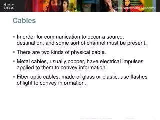
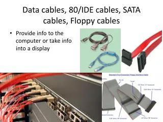
CABLES, INSULATION RESISTANCE. (Adapted from:D.T. Hall:Practical Marine Electrical Knowledge). Shipboard cables.

E N D
CABLES, INSULATION RESISTANCE (Adapted from:D.T. Hall:Practical Marine Electrical Knowledge)
Apart from an IR (megger) test on a main cable run (e.g. along the flying bridge of a tanker) the survey of cables and their installation is largely based on a close visual examination. • Inspection would search for any external damage of a cable's outer sheath and wire or basket weave armouring (if fitted). • The cable must, of course, be adequately supported along horizontal and vertical runs by suitable cable clips or ties.
A flying bridge is a (usually open) area on top of, or at the side of, a ship's pilothouse, or closed bridge, that serves as an operating station for the ship's officers in good weather or when maneuvering in port, where good views along the ship sides are important. It is also a raised, usually second story cockpit on a smaller boat, such as a sport-fisher.
Where cable-runs along an open deck have expansion loops, these must be examined for abrasion and wear. • Where cables pass throughfire check bulkheads they must be correctly glanded or pass through stopper boxes which prevent the passage of fire between compartments.
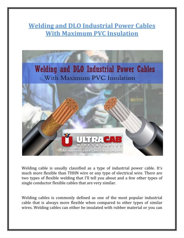
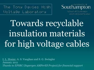
Probably the most common ship-board cable insulations used are EPR (ethylene propylene rubber) or butyl rubber which is sheathed with either PCP (poly- chloroprene) or CSP (chlorosulphonatedpolyethelene).
EPR or butyl rubber are good electrical insulators but are not mechanically strong or resistant to oil. This is why a sheath of PCP or CSP (which is stronger and has greater oil and fire resistance) is fitted around the inner insulation.
Where EPR/butyl cable terminations may be subjected to oil vapour it is usual to tape or sleeve the cable ends to prevent deterioration of the insulation. Check that such taping is secure.
Flexible cables to light fittings, power tools, etc., should be inspected formechanical damage. In normal operation a flexible cable may be repeatedly dragged and chafed so reducing its safety. If in doubt replace flexible cables. • A copper strap or flexible earthing braid/wire is used to bond the steel frame of all electrical motors and other equipment to the ship's hull.
Without an earth strap, a loose internal wire may touch the frame causing it to becomelive at mains voltage with obvious danger to operators. The earth strap electricallyanchors the frame to the ship's hull (zero volts) to eliminate the shock hazard to personnel.
Insulation Resistance • The surveyor will require a list which shows the results of recent insulation tests on all main 440 V and 220 V circuits. • Such a list should also indicate the test dates, weather conditions (hot, humid, etc.) together with any comments relevant to the test conditions (e.g. machine hot or cold).
For essential items such as generators and main motors, the surveyor will be more interested in the IR trend, so a set of past results showing the insulation history of such machines may be requested.
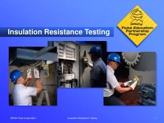
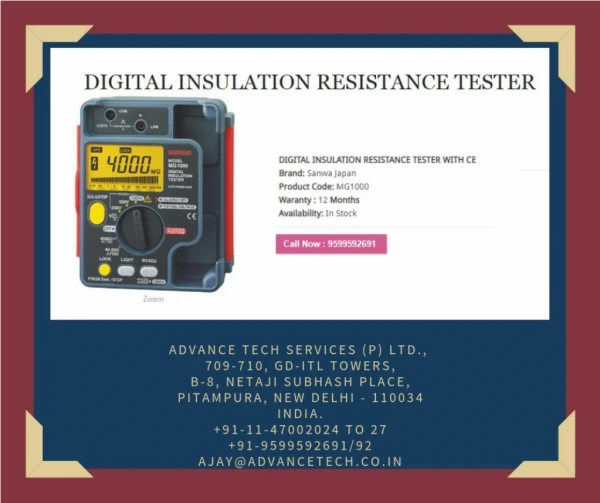
Insulation resistance is one of the important readings of marine electrical equipment systems and serves as the best guide to indicate the health of the equipment. Insulation resistance is measured between the insulated conductors and earth and between conductors. • The insulation resistance is measured by the equipment known as megger, which is a high resistance meter with a test voltage of about 500 volts dc. The 500 V is produced with the help of a hand driven generator or with the help of batteries and electronic voltage charger. • The 500 V test charge is suitable for testing equipments which are rated for 440 volts AC. The equipments to be tested for insulation resistance must be disconnected from the live power supply and the supply to be locked down to prevent any accidents. • Read more: http://www.marineinsight.com/tech/marine-electrical/importance-of-insulation-resistance-in-marine-electrical-systems/#ixzz1tAxdWcC7
On ships, the insulation resistance of all the motors is checked from time to time and values are logged as a part of planned maintenance system. The insulation resistance of the machinery reduces with increase in temperature. The reasons for increase in temperature may be due to dust deposits on the windings or improper ventilation. The resistance is checked between the windings U-V, V-W, W-U and between U & earth, V& earth, W& earth.
The readings are logged down and the graph is plotted and the trend of insulation resistance is checked. If the reading is reduced to a very low value then the windings have to be checked and cleaned and the readings are to be taken again. Read more: http://www.marineinsight.com/tech/marine-electrical/importance-of-insulation-resistance-in-marine-electrical-systems/#ixzz1tAyKxORb