Download
1 / 40
400 likes | 594 Views
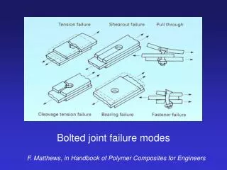
Modular Coil Assembly Bolted Joint PDR 2/22/07. Objectives. The review objectives include... Define the location of additional inboard bolts Finalize the material selection and design of the shim and washers Establish the minimum bolt preloads for both types of joint

E N D
Modular Coil Assembly Bolted Joint PDR 2/22/07
Objectives • The review objectives include... • Define the location of additional inboard bolts • Finalize the material selection and design of the shim and washers • Establish the minimum bolt preloads for both types of joint • Establish the adequacy of the bolted joint design through analysis • consistent with NCSX Structural and Cryogenic Design Criteria and • the NCSX Handbook for Bolted Joint Design • Document the envisioned assembly sequence and assembly requirements
Three-Coil Assembly C-C B-C A-B A-A
Interface A-B • 25 tapped holes, most on Type-A • 1 through hole Type-B Type-A
Interface B-C • 29 tapped holes, most on Type-B Type-C Type-B
Interface A-A • 20 tapped holes
Interface C-C • 24 through holes • 8 tapped holes
A1 Welded Adaptor w/ Tapped Hole A-B 2 plcs A-B 3 plcs A-A 4 plcs
Assembly Requirements • Position the coils accurately • Minimize gaps
Assembly Sequence insulating bushing insulating layer 1- Position coils and measure shim 2- Fabricate and install shim
Assembly Sequence (2) Insulating washer 3- Position coils and measure bushing 4- Fabricate and install bushing
Assembly Sequence (3) 5- Install ½ in. thk load washer 6- Install spherical washers & nut
Bolt Tightening (1) • CAD model layout of wrenches has been performed • Options include low-profile torque wrench, supernut, hydraulic tensioner • Hole catalog being developed by visual inspection, template checking Table A-B based on CAD layout low profile torque wrench
Bolt Tightening (2) Supernut Dw=2.5-in D= 2.46-in L=1.93-in T= 1.75-in A286 (4340 is std) Table B-C based on CAD Layout
Bolt Tightening (3) Table C-C based on CAD layout
Bolt Tightening (4) Table A-A based on CAD layout
Bolt Tightening (5) • Layout of hydraulic tensioner is in progress 4.6 DIA 4.9
Bolted Joint Parameters (1) MATERIALS-
Bolt Preload • Nominal preload of 75-kips based on 85% of A286 yield strength • Cool-down relaxation is -4% with Inconel load washer, +2% with Titanium • Preload uncertainty for hydraulically tensioned studs w/ ultrasonic inspection
Joint Stiffness min preload joint separates at 90-kip
Maximum Shear Load • Local model analyzed for 25-kips shear • Max bushing stress is 67.4-ksi • Compare to bushing material: • Compressive strength = 60-ksi • Min bearing strength = 30-ksi • Max shear load = ~11-kip Through hole Local FEA model Tapped hole
abint abinb Global Analysis w/ Bonded Flange Joint • Three coils w/ rotational bc, bonded flange joint, 2T EM load • Shear, normal force by region determines required friction coefficient • Clamping force increased by addition of inboard bolts compression (blue) without inb bolts inboard regions with inb bolts bolts added Interface A-B Normal pressure mu to prevent slip
Global Analysis (2) • Additional inboard bolts reduces required coefficient of friction to 0.45 • Bolts added to A-B (3), B-C (4), and A-A (2) interfaces
Friction Testing • Friction tests with diamond, alumina shim coatings can increase mu to ~0.5 • Design criteria limits value to 2/3 achievable or 0.3 Standard shim concept Additional bolts Custom shims at interface B-C
Location of Inboard Holes (1) Type-A, Flange Datum-D, Winding Side-A
Location of Inboard Holes (2) Type-A, Flange Datum-E, Winding Side-B
Location of Inboard Holes (3) Type-B, Flange Datum-D, Winding Side-A
Location of Inboard Holes (4) Type-B, Flange Datum-E, Winding Side-B
Location of Inboard Holes (5) Type-C, Flange Datum-D, Winding Side-A
Global Analysis w/ Equivalent Bolt Model • Three coils w/ rotational bc, discrete attachments, sliding interface, 2T EM load • Inboard bolts added, mu=0.3 • Results show slipping w/ “residual” shear load taken by bolts • Some shear loads >11-kips limit for bushing Interface A-B
Global w/ Bolts (2) Interface B-C
Global w/ Bolts (3) • Load step difference (preload/EM) used to determine alternating bolt load • Results preliminary, but suggest alternating load is ~8% of preload Interface A-A
Global w/ Bolts (4) • No problem here Interface C-C
Conclusion • Minimum friction condition (mu=0.3) does not work for all bolts, however • both analyses indicate that the friction coefficient seen in testing is adequate • Tests of bolted joint mockups are planned • Additional analysis needed to check joint fatigue life LVDT connecting rods Test joint Shear Test Setup -K Freudenberg
Conclusion (2) • The review objectives include... • Define the location of additional inboard bolts • Hole location drawings are being prepared. • Finalize the material selection and design of the shim and washers • Hardware models/drawings are in final final checking for • procurement of tension and shear test joint components. • Establish the minimum bolt preloads for both types of joint • Preload defined according to design criteria. • Access and tooling for bolt tightening is being evaluated. • Establish the adequacy of the bolted joint design through analysis • consistent with NCSX Structural and Cryogenic Design Criteria and • the NCSX Handbook for Bolted Joint Design • Bolt and joint have been shown to have adequate strength if friction • is increased or other shear constraint is considered. • Fatigue evaluation is in progress. • Document the envisioned assembly sequence and assembly requirements • Basic assembly sequence has been defined, but details TBD. • Hole catalog and planned coil-to-coil fitup tests are critical.