Download
1 / 33
410 likes | 1.01k Views
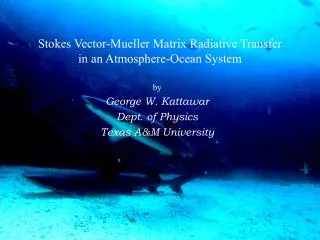
Stokes Vector-Mueller Matrix Radiative Transfer in an Atmosphere-Ocean System. by George W. Kattawar Dept. of Physics Texas A&M University. Why do Polarimetry?. It is the only correct way to do radiative transfer

E N D
Stokes Vector-Mueller Matrix Radiative Transfer in an Atmosphere-Ocean System by George W. Kattawar Dept. of Physics Texas A&M University
Why do Polarimetry? • It is the only correct way to do radiative transfer • In 1947 Karl von Frisch showed that honey bees (Apis mellifera) used polarized light for navigation • More recently, Rüdiger Wehner showed that certain ants also use the sun as a compass and studied the neurophysiology of their vision • Talbot Waterman showed that a variety of crustaceans, squids, octopuses, and fishes are able to detect the orientation of the electric vector of linearly polarized light • Humans can see a faint image called Haidinger’s brush when viewing the clear zenith sky at sunrise or sunset • Circular or elliptical polarization is rare in nature; however, it occurs just inside the critical angle for internally reflected light. Also a family of beetles called Scarabaeidae convert unpolarized light into left circularly polarized light
Plankton as viewed by a squid Planktonic animal as seen through "regular" vision As seen when placed between two crossed linear polarizing filters As seen by putting the two polarizers at 45° to each other
Photo taken with circular polarized light for illumination and a circular analyzer for viewing Contrast enhancement using polarization Photo taken with a flash lamp and no polarization optics
What are the optically significantconstituents of ocean water? Water (of course) Dissolved Organic Compounds (CDOM, gelbstoff, gilvin) Bacteria Phytoplankton Larger Organic Particles (zooplankton, “marine snow” – amorphous aggregates of smaller particles) Inorganic particles (quartz sand, clay minerals, metal oxides)
DOP= Degree of polarization= DOLP = Degree of linear polarization = I is the radiance (this is what the human eye sees) Stokes vector and polarization parameters Qis the amount of radiation that is polarizedin the0/900 orientation U is the amount of radiation polarized in the +/-450 orientation V is the amount of radiation that is right or left circularly polarized DOCP = Degree of circular polarization = |V|/I Orientation of plane of polarization = = tan-1(U/Q) Ellipticity= Ratio of semiminor to semimajor axis of polarization ellipse=b/a =tan[(sin-1(V/I))/2]
Nissan car viewed in mid-wave infrared Q U I V This data was collected using an Amber MWIR InSb imaging array 256x256. The polarization optics consisted of a rotating quarter wave plate and a linear polarizer. Images were taken at eight different positions of the quarter wave plate (22.5 degree increments) over 180 degrees. The data was reduced to the full Stokes vector using a Fourier transform data reduction technique.
Scattering Geometry Scattering object Incident beam Scattering angle Scattering plane Scattering amplitude matrix
M is called the Mueller matrix The electric field can beresolved into components as follows: E = El l+ Er r Where El and Er are complex oscillatory functions. The four component Stokes vector can now be defined as follows: Stokes vector-Mueller matrix formulation They are all real numbers and satisfy the relation I2 = Q2 + U2 + V2
Symmetry Operations Hi: I am a particle Reciprocal position Mirror image For randomly oriented particles with their mirror images in equal numbers
Rotation Matrices Rotation matrix leaves I, Q2+U2 and V invariant
Polarizer and analyzer settings for Mueller matrix measurements Diagram showing the input polarization (first symbol) and output analyzer orientation (second symbol) to determine each element of the MSMM denoted by Sij. For example, HV denotes horizontal input polarized light and a vertical polarization analyzer. The corresponding symbols denoting polarization are V, vertical; H, horizontal; P, +45, M, -45; R, right handed circular polarization; L, left handed circular polarization; and O, open or no polarization optics. This set of measurements was first deduced by Bickel and Bailey..
Consider a beam of light passing though a small volume of water with no absorption or scattering Let’s add some absorption to the water Now add scattering: Light can scatter out of the beam into a different direction And into the beam from a different direction The Radiative Transfer Process
Monte Carlo Method: the Good News and the Bad News First the Good News • Can handle virtually any geometry • Can calculate both vector and scalar results simultaneously • Can handle several different phase functions, single scattering albedos, and ground albedos simultaneously in a single run • Detectors can be placed at any position and in any direction in the atmosphere-ocean system. There is no bin-averaging with this method • Easy to calculate order of scattering contributions to final result. This allows a more reasonable meaning of “level of line formation” in spectroscopy of planetary atmospheres Now the Bad News • Since calculation is statistical in nature, results are always subject to statistical uncertainty • Slow compared to other methods; however, Monte Carlo calculations are trivial to parallelize
Biased Sampling Consider the expectation value of some function f(x) p(x) is the probability density function and f(x) is called the estimator Now suppose we want to sample from Bivariate density function (1) With backward Monte Carlo we cannot sample above density function since we do not know In, Qn, and Un so we are forced to usebiased sampling. We therefore sample F uniformly between 0 and 2p and Q according to the density function S11. To remove the bias we must therefore divide Eq. (1) by S11 This leads to the use of the reduced Mueller matrix where all elements are divided by S11.
Direct sunlight skylight Strong elliptical polarization Optical thickness of atmosphere = 0.15 Region of total Internal reflection Optical thickness of ocean = 1.0 n = 1.338
Multicomponent approach to light propagation with full Stokes vector treatment • Method developed by Eleonora Zege’s group in Minsk, Belarus • Applicable to scattering media containing clouds, mists, and ocean water • Computes all 16 elements of Green matrix for any set of polar and azimuthal angles • In each altitude dependent sub-layer, aerosol scattering and absorption as well as molecular scattering and absorption are accounted for • Cloud layers can be handled • Underlying surface can be included with a bi-directional reflection matrix with the small-angle component in the vicinity of the specular reflection • Can handle both smooth and wind-ruffled interface characterized by specifying both wind velocity and azimuth
Original VRTE Flow chart of RayXP program Small angle VRTE Diffusion VRTE 3-separate small-angle equations Equation for small-angle non-diagonal terms Conventional VRTE with smooth kernel General solution
Backward Monte Carlo Calculation Incoming irradiance Earth Atmosphere
Conclusions • Mueller matriximaging allows us todetect objects at further distances and see surface features in turbid media when compared to normal radiance measurements • It can be a very powerful tool in identifying and characterizing both anthropogenic and natural aerosols including bioaerosols • It may also prove to be a very useful tool for the screening of precancerous skin lesions • We now have codes that can calculate the full MSMM (Green matrix) for any geometry and source detector configuration