Download

1 / 18
300 likes | 1.15k Views
Understanding Spacer Shaft Alignment. Applying Tolerances the Right Way Alan Luedeking. Suppose you had this misalignment. [please click]

E N D
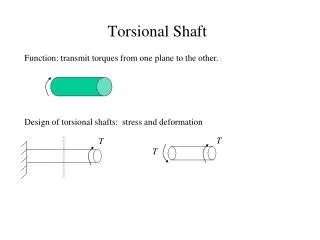
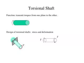
Understanding Spacer Shaft Alignment Applying Tolerances the Right Way Alan Luedeking
Suppose you had this misalignment. [please click] The light blue dotted line that will appear shows you how much offset you have between the shafts at the coupling. [please click, and watch the graphic] The green bracket shows you how much offset is the most you can have, high or low. This is your offset tolerance, when short coupled (with the shafts close together.)
These green lines show you what the worst angleis that you can have. This is your angularity tolerance. Now suppose you were to pull the angled shaft on the rightaway from the stationary shaft on the left. You still keep exactly the same offset that you had before, and angle too.
Now you need something to connect the ends of your two shafts together. This is called your spacer shaft. (This spacer shaft is also called a jackshaft if it is long, or a spoolpiece if it is short.) This is the angle needed on the left side between the spacer shaft and the stationary shaft, in order for the spacer shaft to rise up enough to connect to the shaft on the right. This angle is defined by the offset on the right, over the length of the spacer.
This is the angle needed on the right side, between the spacer shaft and the shaft on the right, in order for the spacer shaft to connect to the stationary shaft on the left. This angle is exactly the same as the offset projected to the left side, between the two shafts’ centerlines, over the length of the spacer.
These green lines represent the maximum angles that your spacer shaft is allowed to have, with respect to your stationary shaft on the left. This means that the offset between the machine on the right and the stationary machine on the left can not be more than what will be shown by the vertical green line which will appear on the right.
These new green lines from the right represent the maximum angles that your spacer shaft is allowed to have with respect to your machine shaft on the right. This in turn means that the projected offset between your machine on the right and your stationary machine on the left is not allowed to be more than what will be shown by the vertical green line which will appear on the left.
These projected offsets mean that your tolerance envelope for a spacer shaft is in fact a rectangular box. What this means is that the projected centerlines of both machines must always fall somewhere inside the box, for you to be well aligned.
The machine on the right needs to come down to achieve a perfect alignment with the machine on the left. But is this really necessary? What if you are base-bound, or bolt-bound?Do you have to make this exact correction to get aligned?
The answer is NO. All you need to do is get the projected centerline “into the box.” Suppose that instead of coming down, you were to raise the back feet instead: You just raised the back feet, without moving the front feet.
Look what this did to your projected offset over on the left side: You got the projected centerline from the right machine into the box! You’re aligned!
Even though the projected offsets on the right and left sides may seem big, they’re just a reflection of the angle between spacer shaft and each machine shaft at the opposite end, and these angles are acceptably small.
Looking at the values of the projected offsets and comparing these to the permissible values in the tolerance table is called the “offset-offset” method. Looking at the values of the angles and comparing these to the permissible values in the tolerance table is called the “angle-angle” method.
24 mils 21 mils 48″ 28.8 mils 28.8 mils SHAFT ALIGNMENT TOLERANCES(SPACER COUPLINGS) Suppose your spacer shaft is 48″ long. Your machine spins 1800 RPM. What is your tolerance for projected offset? 48 inches × 0.6 mils per inch = 28.8 mils. This value represents the boundaries of your tolerance envelope: the green box. The red offset on the right is 21 mils. The blue offset on the left is 24 mils. You are aligned, in the box!
21 mils 48″ 0.5 mils/inch 24 mils 0.4375 mils/inch SHAFT ALIGNMENT TOLERANCES(SPACER COUPLINGS) The angular- itytolerance for spacer shafts at 1800 RPM is 0.6 mils per inch. The red angle on the left is:21 mils ÷ 48 inches = 0.4375 mils per inch. The blue angle on the right is:24 mils ÷ 48 inches = 0.5 mils per inch. Each of the angles is less than 0.6 mils per inch. You are aligned, in the box!
Knowing how to align spacer shafts to the right tolerance will save you time!