Download
1 / 48
480 likes | 666 Views
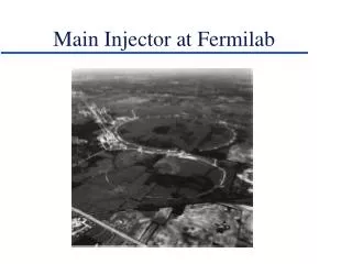
Main Injector at Fermilab. Silicon Vertex Tracker. Integrated system of barrels and disks ~ 800k total channels. Silicon Tracker Layout. 1/7 of the detector (large-z disks not shown). 387k ch in 4-layer double sided Si barrel (stereo). 405k ch in interspersed

E N D
Silicon Vertex Tracker Integrated system of barrels and disks ~ 800k total channels
Silicon Tracker Layout 1/7 of the detector (large-z disks not shown) 387k ch in 4-layer double sided Si barrel (stereo) 405k ch in interspersed disks (double sided stereo) and large-z disks
Silicon Tracking System 1/2 of detector 50 cm 1.1 1.7 Silicon Tracker 3 7 barrels 12 Disks “F” 8 Disks“H”
Central Fiber Tracker Layout • 8 nested cylinders • radius = 20 ® 51 cm • Each layer • 1 axial doublet • 1 stereo (u or v) xu - xv - xu - xv - …. Constant angle = 3o • Layers • 1,2 - 1.8 m long • 2,8 - 2.6 m long • Total channel count »77K • Clear fiber brings signal to VLPCs - 7 - 11m
Why a Fiber Tracker? A SciFi Tracker provides the following features: • Fast response • Good granularity • Track triggering at Level 1 • High efficiency • Accurate rposition measurement • Compact design • Seamless coverage
A Little History • Snowmass 1984 - Binnie, Kirkby, Ruchti propose inner tracker for SSC based on 25 mm scintillating glass fibers. II + CCD readout • CERN, 1988-1990 - Wood (and the rest of UA2) run with SFD, 60,000 1mm plastic fibers with II + CCD readout • FNAL, 1988 - Reucroft and Ruchti co-chair workshop on SciFi detector development for the SSC • CERN, 1989 - ?? - Taylor (and the rest of L3) run with PSF detector to calibrate the TEC. 3,600 plastic fibers coupled to MCP phototubes • Snowmass 1990 - A scintillating fiber outer tracker is proposed for the DØ upgrade at the Tevatron • Notre Dame 1993 - Tests of Kuraray fiber doped with PTP+3HF and read out by a VLPC demonstrate sufficient light yield for fiber tracking • FNAL, 1994-1995 - A 3,000 channel cosmic ray test of scintillating fibers read out by VLPCs measures high light yield, good position resolution and long-term stability of the VLPC system
A Little History • Snowmass 1984 - Binnie, Kirkby, Ruchti propose inner tracker for SSC based on 25 mm scintillating glass fibers. II + CCD readout • CERN, 1988-1990 - UA2 runs with SFD. 60,000 1mm plastic fibers with II + CCD readout • CERN, 1989 - L3 runs with PSF detector to calibrate the TEC. 3,600 plastic fibers coupled to MCP phototubes • Snowmass 1990 - A scintillating fiber outer tracker is proposed for the DØ upgrade at the Tevatron • Notre Dame 1993 - Tests of Kuraray fiber doped with PTP+3HF and read out by a VLPC demonstrate sufficient light yield for fiber tracking • FNAL, 1994-1995 - A 3,000 channel cosmic ray test of scintillating fibers read out by VLPCs measures high light yield, good position resolution and long-term stability of the VLPC system
Key Features of the CFT • Scintillation dyes - 1% PTP + 1500 PPM of 3HF • Fiber construction - 830 m PS core, multiclad • Photodetectors - Visible Light Photon Counter • Fiber ribbon manufacture - grooved jig plate • Fiber ribbon placement - located with CMM • Fiber-to-fiber connectors - curved, grooved, diamond finished • Support cylinders - double-walled carbon fiber
Visible Light Photon Counters • Key features of the VLPC • Solid state detectors of photons, manufactured at Boeing (originated at Rockwell International) • Operate at the temperature of a few degrees Kelvin • Capable of detecting single photons • High quantum efficiency for photon detection ~80% • High gain ~40 000 electrons per converted photon • Low gain dispersion • Can operate in a high background radiation environment • Used for CFT, CPS and FPS
VLPC Operation • Based on the phenomenon of Impurity Band Conduction, occurring when a semiconductor is heavily doped with shallow donors or acceptors • Electrical transport occurs by charges hopping from impurity site to impurity site • In the VLPC for DØ silicon heavily doped with arsenic atoms • Impurity band 0.05 eV below the conduction band • Normal 1.12 eV valence band used to absorb photons • The 0.05 eV gap used to create an electron-D+ avalanche multiplication • Small gap means low field needed
E field D+ flow Undoped Silicon Doped Silicon Layer VLPC Operation Cross Section Electric Field Distribution Spacer and Substrate Intrinsic Gain Drift Region Region Region • e • h • - • + Photon
VLPC Development History • 1987 published paper on SSPM Solid State Photo-Multipliers • sensitive into infra-red region • 1989 HISTE Proposal Submitted High-Resolution Scintillating Fiber Tracker Experiment • Main goal: to suppress sensitivity in infrared region • 1991-1992 HISTE I, HISTE II, HISTE III • 1993 HISTE IV • Visible QE ~60%, Cosmic Ray Test at Fermilab • 1994 HISTE V High QE High Gain • HISTE VI large scale production based on HISTE V
HISTE-VI VLPC chip • 1 mm pixels • 2x4 array (HISTE-VI)
1024 VLPC pixels in one cassette Electronic readout: custom SVXII chips 3’ VLPC Cassette and Readout
VLPC Production at Boeing • 13 300 needed including 10% spares • 17 845 tested • 15 529 accepted • Yield: 87%
Fiber Placement Inherent fiber doublet resolution is on the order of 100 microns • want to know fiber locations to < 50 microns However, for the Level 1 trigger must place fibers with a skew < 40 microns end-to-end • implications for ribbon fabrication, ribbon mounting and cylinder construction
CFT Track Trigger Trigger response for Z®ee with 4 min.bias (1) Fiber light signals electronic signals (2) Feed all axial fibers into logic gates/cells in Programmable Logical Devices (3) Fiber hit pattern recognition to look for tracks consistent with momentum PT > 1.5 GeV/c (4) Send out the track information to outside L1 CFT
Fiber Ribbon Fabrication • Doublet ribbons of 2 128 fibers • Flexible grooved Delrin plate locates fibers • Aluminum curved back plate sets the radius • Same mold used for ribbon mounting
Fiber Ribbon Fabrication • Doublet ribbons of 2 128 fibers • Flexible grooved Delrin plate locates fibers • Aluminum curved back plate sets the radius • Same mold used for ribbon mounting
The problem with Torlon • During assembly of cylinder 3, interference between ribbon connectors observed • Torlon connectors had grown! • Humidity effect • Studies inconclusive, so … • Torlon has now been rejected • Barrels 7,8 will use aluminum connectors • Other barrels, either Al or Techtron
CFT Support Cylinders • Fabricated “in house” at Fermilab • Double wall design - carbon fiber walls with Rohacell core • Built up on precision steel mandrels
Status - Ribbon Mounting • Ribbon Mounting machine/tooling complete • Test Ribbons have been mounted • Look good • Still need alignment correction (CMM) at 150 mm level - spec 25 mm
Ribbon Mounting Cylinder 3B completed - 30 ribbons total 36 m rms
Fiber Mapping and Routing Long clear waveguide bundles map 256 fibers from SciFi ribbon to 2 128 connectors at VLPC end • Bundles vary from 7-12 meters • Must be light-tight, flexible, narrow, flame retardant and “custom-shaped” at curved end • Mapping of axial fibers critical to trigger • Out of 300 bundles, nearly 100 are unique
CFT Calibration Uses flat optical panel + LED to illuminate fibers from above. One panel for each of 300 ribbons. LED Flat Panel
Flat Optical Calibration Panels • 300 panels total in system • Panels are inexpensive, uniform, made to order Panel Uniformity
Calibration Mounting Scheme SciFi Ribbons • Each ribbon lit by up to 3 panels • Redundancy • Large dynamic range • Each LED output is variable • Panels at both ends detector LEDs Flat Panels
Status and Summary • DØ upgrade progressing - ready for physics in early 2001 • Central Fiber Tracker in production • fabrication complete in April 2000 • cabling completed in summer 2000 • Silicon tracker inserted in fall 2000 • commission with cosmic rays from summer 2000 until start of Run II
CFT Status - Waveguides • Fiber sorted • Best (attn.L from Kuraray) - longest runs [8-11.5m] • Connectorization • At ND + Fermilab +IU • QC with x-ray source at Lab3 • Expect to complete production in August
CFT Status - Tracker Mechanical Complete Global precision »33mm(Measured vs Desired)
CFT Status - Waveguides • Fiber sorted • Best (attn.L from Kuraray) - longest runs [8-11.5m] • Connectorization • At ND + Fermilab +IU • QC with x-ray source at Lab3 • Expect to complete production in August
Fiber Tracker Layout • Axial doublet layers on each of 8 cylinders • Alternate u or v stereo layers on successive cylinders • ~ 78k total channels