Download
1 / 31
2.3k likes | 5.25k Views
Fundamentals of Semiconductors. Definition. A semiconductor is a material that is an insulator at very low temperature, but which has a sizable electrical conductivity at room temperature .

E N D
Definition • A semiconductor is a material that is an insulator at very low temperature, but which has a sizable electrical conductivity at room temperature. • A semiconductor is a substance, usually a solid chemical element or compound, that can conduct electricity under some conditions but not others, making it a good medium for the control of electrical current.
The semiconductor name derives from the materials ability to sometime be a conductor to electricity and other times act as nonconductor to electricity. • The earliest semiconductor material was germanium built into a single with one function (referred as discrete component). • Nowadays, greater than 85% of all microchips are made from silicon semiconductor material.
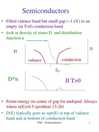
Introduction • The distinction between a semiconductor and an insulator is not very well-defined, but roughly, a semiconductor is an insulator with a band gap small enough that its conduction band is appreciably thermally populated at room temperature. • It has a resistivity between that of conductor and insulator.The resistivity of a semiconductor decreases as temperature increases. So at higher temperatures semiconductor act like conductors and at lower temperatures they act like insulator.
Its conductance varies depending on the current or voltage applied to a control electrode, or on the intensity of irradiation by infrared (IR), visible light, ultraviolet (UV), or X rays • Silicon dioxide is an example of a nearly-perfect insulator, while silicon is the archetypical semiconductor. • Many materials that in the past would have been considered insulators are now called wide bandgap semiconductors.
Semiconductor material do not have free electrons to support the flow of electrical current through them at room temperature. • However, valence electron may become free electrons if sufficient energy is induced into the material, for example by heating the material. • The specific properties of a semiconductor depend on the impurities, or dopants, added to it.
An N-type semiconductor carries current mainly in the form of negatively-charged electrons, in a manner similar to the conduction of current in a wire. • A P-type semiconductor carries current predominantly as electron deficiencies called holes. A hole has a positive electric charge, equal and opposite to the charge on an electron.
Elemental semiconductor include: • Antimony - germanium, • Arsenic - selenium • Boron - silicon • Carbon - sulfur • Silicon is the best-known of these, forming the basis of most Integrated Circuits (IC) • Common semiconductor compounds include:- • gallium arsenide • indium antimonide • the oxides of most metals • gallium arsenide (GaAs) is widely used
Intrinsic semiconductors (Pure Silicon) • An intrinsic semiconductor(intrinsic silicon) is one which is pure enough that impurities do not appreciably affect its electrical behavior. • In this case, all carriers are created by thermally or optically exciting electrons from the full valence band into the empty conduction band. • The band gap, or energy spacing between the valence band and the conduction band, corresponds to the energy necessary to free charge carriers in this way.
Si Si Si Si Si Si Si Si Si Si Si Si Intrinsic semiconductors (Pure Silicon) Covalent Bond Silicon crystal with covalent bonds between silicon (Si) atoms, for a pure semiconductor without doping
Doped • The structure of silicon can be altered to greatly enhanced its conductivity by adding small amounts of other elements to the material through a process known as doping. • Doping is the process of adding certain elements to pure silicon to improve the conductivity of the semiconductor. • The elements added during doping are referred to as dopants or impurities because the silicon is no longer pure.
Doped (Cont.) • The more impurity added then the higher the conductivity ( or the lowest resistivity). • The term impurity used to indicate that another element have been added to the silicon. • Doped silicon is also known as extrinsic silicon.
Doped (Cont.) • Two kinds of impurities are used: • The impurities with five valence electrons in the outer ring are called “donors.” The semiconductor material doped with a donor impurity is known as n-type semiconductor material. Phosphorous, Arsenic, and Antimony are examples of donor impurities. • The impurities with three valence electrons in the outer ring are called “accepters.” The semiconductor material doped with an accepter impurity is known as p-type semiconductor material.
Doped (Cont.) Atomic structure of the Silicon Atom
N-type Semiconductors • The doping element can be arsenic, antimony, or phosphorus which have an electron valence of 5. This value means one extra electron for each group of four in the outermost shell of the atom. • As a result, each impurity atom provides an extra electron in the covalent bonds. Figure 1.0 show silicon with atomic number 14 doped with phosphorus (P), which has atomic number 15 and 5 valence electron. • Four of these become part of covalent bond structure. The extra electron can be considered as a free negative charge. The result is N-type doped silicon.
- N-type Semiconductors (Cont’d) Negative aluminium ion Free negative electron charge Si P Si Si Figure 1.0 Crystal lattice structure of Si atoms doped with phosphorus (P). The covalent bonds have one free electron for each phosphorus atom Si Si Si Si Covalent Bond Si Si Si Si
P-type Semiconductors • The doping element can be aluminum, boron, gallium or indium which have a electron valence of 3. Each atom has three electrons in the outermost ring. • Figure 2.0 show silicon doped with aluminum (Al). The element Al has atomic number 13, which means three outer electrons. • In the covalent bonds of Al and Si atoms, there are seven electrons instead of eight. The one missing electron in covalent bond can be considered as a free positive charge, called a hole. • With many aluminum atoms added, the doping provide many hole charges. The hole are free charges that can move with relative ease to produce electric current. • The result is P-type doped silicon.
P-type Semiconductors (Cont’d) Positive phosphorus ion Free positive hole charge Al Si Si Si Figure 2.0 Crystal lattice structure of Si atoms doped with Aluminium (Al). The covalent bonds have one free positive hole charge for each aluminium atom + Si Si Si Si Covalent Bond Si Si Si Si
PN Junction • When p-type semiconductor is placed next to an n-type semiconductor, thus forming a “junction.” • At the junction some of the free electrons from the n-type semiconductor cross the junction and fill the holes. • This movement of electrons across the junction leaves the region in n-type semiconductor adjacent to the junction with excess positive charge. • The electrons filling the holes in the region adjacent to the junction on the p-type semiconductor create excess negative charge. • Figure 3.0 shows the dynamics of a p-n junction. This oppositely charged region on both sides of the junction, known as the “depletion region,” creates a potential barrier, which is 0.7 volts for Silicon based semiconductor and 0.2 for Germanium based semiconductor.
Depletion Region P-type material PN Junction (Cont’d) Electron jumping across The junction to recombine With a hole N-type material Junction Figure 3.0:The PN Junction
Forward Biased PN Junction • If we connect the positive and negative terminals of a power supply to the p-type and n-type semiconductors, respectively, the junction is said to be forward-biased. • Figure 4.0 shows the dynamics of the junction under this condition. • When the potential applied across the p-n junction is sufficiently high (greater than 0.7 volts for Silicon based semiconductor and greater than 0.2 volts for the germanium based semiconductor), the free electrons from the n-type material will be able to jump across the depletion region and go towards the positive terminal of the power supply. • This causes the IDto flow through the p-n junction, from positive terminal to the negative terminal of the power supply.
Electron jumping across The junction to recombine With a hole Depletion Region Forward Biased PN Junction (Cont’d) With sufficiently high potential In forward-biased junction, free electrons will jump across the depletion region to form a flow of electrical current Junction Figure 4.0:A forward biased PN Junction
Reversed Biased PN Junction • If we connect the positive and negative terminals of a power supply to the n-type and p-type semiconductors, respectively, the junction is said to be reverse-biased. • Figure 5.0 shows the dynamics of the junction under this condition. • When the potential applied across the p-n junction with this polarity, the free electrons in the n-type semiconductor are attracted towards the positive voltage and move away from depletion region. • The holes on the p-type semiconductor are attracted to the negative terminal of the power supply. • This, in effect, widens the depletion region and essentially makes it impossible to have a current flow from positive terminal to the negative terminal of the power supply. • In this way, a p-n junction (diode) essentially acts like a valve, in which air can be pumped in one direction but cannot come out (flow) in the other direction.
Hole moving towards the negative terminal leaving a wider negatively charged depletion region (no holes) on the P-type material Reversed Biased PN Junction (Cont’d) Free electrons moving towards the positive terminal leaving a wider positively charged depletion region (no free electrons) on the N-type material N-type material P-type material Junction Depletion Region widens Figure 5.0:A reversed biased PN Junction
Half Wave Rectifier • The behavior of the p-n junction under forward -and reverse-biased conditions is very useful in several applications. • Consider one such application known as rectification. • Rectification is a process of converting an AC signal to a DC signal. • Figure 6.0 shows a simple circuit of a rectifier. • This particular rectifier is called half-wave rectifier as it only produces the positive half cycle of the input signal at the output of the rectifier. • Note that during the positive half cycle, the diode is forward biased and the current IDflows through the diode. • During the negative half cycle, however, the diode becomes reverse-biased and prevents the current flow through the diode.
Half Wave Rectifier (Cont’d) Figure 6.0