Download
1 / 15
160 likes | 526 Views
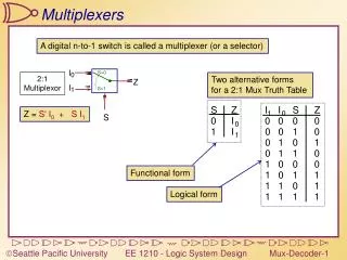
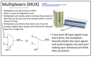
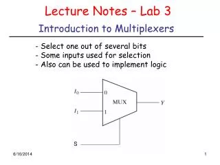
Lecture Notes – Lab 3. Introduction to Multiplexers. - Select one out of several bits - Some inputs used for selection - Also can be used to implement logic. S. Lecture Notes – Lab 3. Introduction to Multiplexers. True Table. Lecture Notes – Lab 3. 4-to-1 multiplexer.

E N D
Lecture Notes – Lab 3 Introduction to Multiplexers • - Select one out of several bits • - Some inputs used for selection • - Also can be used to implement logic S
Lecture Notes – Lab 3 Introduction to Multiplexers True Table
Lecture Notes – Lab 3 4-to-1 multiplexer
Lecture Notes – Lab 3 4-to-1 multiplexer
Lecture Notes – Lab 3 4-to-1 multiplexer – VHDL Implementation Architecture ARCHITECTURE multiplexor4x1 OF mux4x1 IS BEGIN PROCESS(S, D0, D1, D2, D3) BEGIN CASE S IS WHEN "00"=> Y <= D0; WHEN "01"=> Y <= D1; WHEN "10“=> Y <= D2; WHEN OTHERS => Y <= D3; END CASE; END PROCESS; END multiplexor4x1; Entity ENTITY mux4x1 IS PORT ( S : IN STD_LOGIC_VECTOR (1 downto 0); D0 : IN STD_LOGIC; D1 : IN STD_LOGIC; D2 : IN STD_LOGIC; D3 : IN STD_LOGIC; Y : OUT STD_LOGIC ); END mux4x1; See details in the file mux4x1.vhd
Lecture Notes – Lab 3 Digital Arithmetic - Addition Block Diagram A S B 1-bit adder C K True Table
Lecture Notes – Lab 3 1-bit Adder Using Two 4-to–1 Mux K-map for S A A’ A’ A 0 A A 1 S S C K-map for C B K B K See VHDL implementation in addition.vhd
Lecture Notes – Lab 3 1-bit Adder Using Two 4-to–1 Mux - VHDL Architecture ARCHITECTURE addition_arch OF addition IS SIGNAL sig1:STD_LOGIC_VECTOR(1 DOWNTO 0); BEGIN sig1(1) <= B; sig1(0) <= K; P1: PROCESS (sig1, A) BEGIN CASE sig1 IS WHEN "00"=> S <= A; WHEN "01"=> S <= NOT(A); WHEN "10“=> S <= NOT(A); WHEN OTHERS => S <= A; END CASE; END PROCESS; P2: PROCESS (sig1, A) BEGIN CASE sig1 IS WHEN "00"=> C <= 0; WHEN "01"=> C <= A; WHEN "10“=> C <= A; WHEN OTHERS => C <= 1; END CASE; END PROCESS; END multiplexor4x1; Entity ENTITY addition IS PORT ( A : IN STD_LOGIC; B : IN STD_LOGIC; K : IN STD_LOGIC; S : OUT STD_LOGIC; C : OUTSTD_LOGIC ); END addition;
Lecture Notes – Lab 3 Digital Arithmetic - Subtraction Block Diagram X D 1-bit subtraction Y B b True Table
Lecture Notes – Lab 3 1-bit Subtraction Using Two 4-to–1 Mux Design a binary Subtractor Using Two 4–to-1 Mux 1- K-map for D 2- Derive the inputs of the mux D 3-K-map for B 4- Derive the inputs of the mux B 5- Implement
Lecture 8 - XOR Gate Operation: XOR (eXclusive OR) Expressions: x y = x’y + xy’ Truth table: Logic gate:
Lecture 8 - XOR Gate • A two-input XOR gate outputs true when exactly one of its inputs is true: • XOR corresponds more closely to typical English usage of “or,” as in “eat your vegetables or you won’t get any pudding.” • Several properties of the XOR operation: x y = x’ y + x y’
More XOR • The general XOR function is true when an odd number of its arguments are true. • For example, we can use Boolean algebra to simplify a three-input XOR to the following expression and truth table. x (y z) = x (y’z + yz’) [ Definition of XOR ] = x’(y’z + yz’) + x(y’z + yz’)’ [ Definition of XOR ] = x’y’z + x’yz’ + x(y’z + yz’)’ [ Distributive ] = x’y’z + x’yz’ + x((y’z)’ (yz’)’) [ DeMorgan’s ] = x’y’z + x’yz’ + x((y + z’)(y’ + z)) [ DeMorgan’s ] = x’y’z + x’yz’ + x(yz + y’z’) [ Distributive ] = x’y’z + x’yz’ + xyz + xy’z’ [ Distributive ] K-map looks like that: yz x
Adders using XOR • A circuit called a full adder takes the carry-in value into account A (B Carry-in)
Parity generation using XOR • For a given number of bits, attach a new bit 0 or 1, in order to ensure that the total number of 1s is even (odd) • Remember the property of XOR: it is true when an odd number of its arguments are true. Receiver detects the error (he computes the XOR of “1111010”, which gives ‘1’. Sender wants to transmit “110101” using even parity. Then, it attach 0 (by computing the XOR of 110101), i.e., “1101010” Channel B A Channel flips a bit: “1111010”